
User Manual

2 • 65-2396RK CO
2
Transmitter
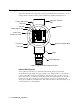
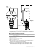
Description
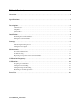
This section describes the components of the CO
2
transmitter. The transmitter is a 4 - 20
mA type detector head. It consists of the CO
2
detector, amplifier, and junction box.
Figure 1: CO
2
Transmitter Component Location
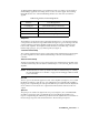
Infrared CO
2
Detector
The CO
2
detector is made up of a miniature infrared CO
2
detector housed and
encapsulated in a pipe nipple. The pipe nipple has 3/4” NPT threads on each end and a
1 1/4” hex that allows removal or installation of the detector with a wrench. A porous
flame arrestor that is coated with a hydrophobic film that repels liquids is on one end of
the detector and allows sample gas to enter the detector. Four color coded leads, red,
white, green, and black, extend from the other end of the detector. The leads allow you to
connect the detector to the amplifier.
57-1053RK
BR W G
S2 001
Controller Terminal
Strip
Amplifier
IR CO2 Detector
J-Box
Detector Terminal Stri
p
ZERO
SPAN
Sensor
Current
mA
Jumper Pins,
Factory Use Only
Factory Adjust Pot
Span Pot
Zero Pot
Factory Adjust Pot
+ Test Point
- Test Point
LEL
S
PWR / SIG