65-2395RK-CH4 Methane Transmitter Operator’s Manual Part Number: 71-0183RK Revision: A Released: 4/12/11 RKI Instruments, Inc. www.rkiinstruments.
WARNING Read and understand this instruction manual before operating transmitter. Improper use of the transmitter could result in bodily harm or death. Periodic calibration and maintenance of the transmitter is essential for proper operation and correct readings. Please calibrate and maintain this transmitter regularly! Frequency of calibration depends upon the type of use you have and the sensor types.
Product Warranty RKI Instruments, Inc. warrants gas alarm equipment sold by us to be free from defects in materials, workmanship, and performance for a period of one year from date of shipment from RKI Instruments, Inc. Any parts found defective within that period will be repaired or replaced, at our option, free of charge.
Table of Contents Overview . . . . . . . . . . . . . . . . . . . . . . . . . . . . . . . . . . . . . . . . . . . . . . . . . . . . . . . . . . . . . . . . . . . 1 Specifications. . . . . . . . . . . . . . . . . . . . . . . . . . . . . . . . . . . . . . . . . . . . . . . . . . . . . . . . . . . . . . . . 1 Description . . . . . . . . . . . . . . . . . . . . . . . . . . . . . . . . . . . . . . . . . . . . . . . . . . . . . . . . . . . . . . . . . . 2 Methane Detector . . . . . . . . . . . . . . . . . . . . .
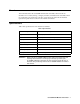
Overview This manual describes the 65-2395RK-CH4 methane transmitter. This manual also describes how to install, start up, configure, maintain, and calibrate the transmitter when it is used with a gas monitoring controller. A parts list at the end of this manual lists replacement parts and accessories for the methane transmitter. Specifications Table 1 lists specifications for the methane transmitter.
Description The 65-2395RK-CH4 methane transmitter is calibrated to methane. The transmitter utilizes an infrared type of detector which has some advantages over a catalytic type of combustible detector. The infrared detector will generally have a longer service life than a catalytic detector, it will require calibration less often, and it can detect combustible gas even if there is no oxygen in the sample which allows detection of combustible gas in an inert atmosphere.
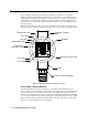
Amplifier The amplifier converts the electrical output from the detector to a 4 to 20 mA signal that corresponds to the detection range and transmits the signal to a gas monitoring controller. A foam gasket that orients the amplifier and keeps it from rotating is installed on the bottom of the amplifier. A label on the amplifier indicates the detector drive current. This drive current is factory set and is dictated by the combustible gas to which the detector is calibrated. Consult RKI Instruments, Inc.
amplifier. Use the top 3/4’’ conduit hub to connect wiring from the amplifier to the controller. Use the cover on the front of the junction box to access the interior of the junction box. The detector and amplifier are factory installed in the junction box. Three spacers installed on the back of the junction box control the distance of the junction box from a mounting surface and ensure that there is enough room to install a calibration cup on the detector during calibration.
2. At the monitoring site you select, hang or mount the junction box with the detector facing down (see Figure 2). Wiring the Methane Transmitter to a Controller WARNING: Always verify that the power to the controller is off before you make wiring connections. 1. Turn off the controller. 2. Turn off or unplug power to the controller. 3. Remove the junction box cover. 4. The detector leads are factory wired.
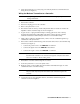
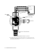
+ 24 VDC 4 - 20 mA In (S) - (DC Ground) Cable Shield Controller or Recording Device J-Box S R W LEL G B PW R / SI G Amplifier (Transmitter) Black Green White Red Detector Wires IR CH4 % Volume Detector Figure 3: Wiring the Methane Transmitter to a Controller 12. If shielded cable is used, connect the cable’s drain wire to an available chassis (earth) ground at the controller. RKI controllers typically have a ground stud that can be used to ground the cable’s drain wire.
Start Up This section describes procedures to start up the methane transmitter and place the transmitter into normal operation. Introducing Incoming Power 1. Complete the installation procedures described earlier in this manual. 2. Verify that the power wiring to the controller is correct and secure. Refer to the controller operator’s manual. 3. Turn on power to the controller. 4. Turn on the controller. 5. Verify that the controller is on and operating properly.
8. Allow the gas to flow for one minute. 9. Verify a voltmeter reading of 100 mV (±2 mV). 10. If necessary, use a small flat-blade screwdriver to adjust the zero pot until the voltmeter reading is 100 mV (±2 mV). 11. Turn the regulator’s on/off knob clockwise to close it. 12. Unscrew the calibration cup from the detector. 13. Unscrew the regulator from the zero air calibration cylinder. For convenience, leave the sample tubing connected to the regulator and the calibration cup. 14.
3. Screw the regulator into the calibration cylinder. 4. Screw the calibration cup onto the bottom of the detector. 5. Use the sample tubing to connect the regulator to the calibration cup. 6. Set a voltmeter to measure in the millivolt (mV) range. 7. Plug the voltmeter leads into the test points on the amplifier. Plug the positive lead into the red (+) test point; plug the negative lead into the black (-) test point. 8.
Table 2:Troubleshooting the Methane Transmitter Condition Symptom(s) Probable Causes Recommended Action Fail Condition • Controller indicates a fail condition. • The transmitter wiring is disconnected or misconnected. • The transmitter’s zero reading is low enough to cause a fail condition. • The transmitter is malfunctioning. 1. Verify that the transmitter wiring is correct and secure. 2. Calibrate the transmitter. 3. If the fail condition continues, replace the detector. 4.
8. Connect the detector leads to the detector terminal strip as shown in Table 3 below and Figure 3 on page 6 of this manual. Table 3:Reconnecting the Methane Detector to the Amplifier 9. Detector Lead Detector Terminal Strip Red %Vol. “R” White %Vol. “W” Green %Vol. “G” Black %Vol. “B” Reinstall the detector terminal strip into its socket. 10. Reinstall the junction box cover. 11. Turn on or plug in power to the controller. 12. Turn on the controller and place it into normal operation.
Table 4:Reconnecting the Amplifier to the Controller Amplifier Controller Terminal Strip Controller Transmitter Terminal Strip (typical) PWR/SIG “-” - (DC -) PWR/SIG “S” S (4 - 20 mA In) PWR/SIG “+” + 24V Table 5:Reconnecting the Detector to the Amplifier Amplifier Detector Terminal Strip Detector Lead DETECTOR “R” RED DETECTOR “W” WHT DETECTOR “G” GREEN DETECTOR “B” BLK NOTE: When a transmitter is first powered up with a new amplifier, the initial output may be either high or below zero d
Calibration Frequency Although there is no particular calibration frequency that is correct for all applications, a calibration frequency of every 6 months is adequate for most infrared methane transmitter applications. Unless experience in a particular application dictates otherwise, RKI Instruments, Inc. recommends a calibration frequency of every 6 months.
Setting the Zero Reading NOTE: If you can verify that the methane transmitter is in a fresh air environment, you do not need to apply zero air to the detector before adjusting the zero reading. 1. Screw the regulator into the zero air calibration cylinder. 2. Use the calibration kit sample tubing to connect the regulator to the calibration cup. 3. Turn the regulator’s on/off knob counterclockwise to open the regulator. 4. Allow the gas to flow for one minute and verify a reading of 100 mV (±2 mV).
Parts List Table 6 lists replacement parts and accessories for the methane transmitter. Table 6:Parts List Part Number Description 06-1248RK Sample tubing (3/16 in. x 5/16 in.; specify length when ordering) 18-0400RK-01 Junction box with spacers 57-1053RK Amplifier with gasket (specify detector part number when ordering) 61-0192RK-CH4 Methane infrared %Vol.