
User Manual

16 • 65-2340RK Toxic Gas Transmitter
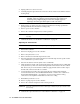
Returning to Normal Operation
1. Remove the voltmeter leads from the amplifier test points.
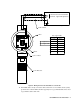
2. Gently pull the calibration cup off of the plug-in sensor
NOTE: For convenience, leave the regulator and calibration cup connected by the
sample tubing.
3. Screw the splashguard firmly back onto the housing cap.
4. Secure the junction box cover to the junction box.
5. When the controller display reading falls below the alarm setpoints, return the
controller to normal operation.
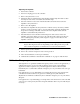
NOTE: If you do not allow the gas reading to decrease below the alarm points, then
unwanted alarms may occur.
6. Verify that the controller display reading decreases and stabilizes at 0 ppm.
7. Store the components of the calibration kit in a safe and convenient place.
Parts List
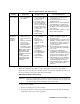
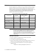
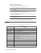
Table 4 lists replacement parts and accessories for the toxic gas transmitter.
Table 4: Parts List
Part Number Description
06-1283RK Calibration kit sample tubing, 3 foot teflon w/flexible tubing on ends
07-0125RK Detector housing cap gasket
18-0400RK-01 Junction box with rubber spacers
57-1064RK-03 S2 series toxic amplifier
65-2300RK-ASH3 Replacement detector assembly, AsH
3
(includes plug-in sensor)
65-2300RK-CL2 Replacement detector assembly, Cl
2
, 0 - 3.00 ppm range
(includes plug-in sensor)
65-2300RK-CL-10 Replacement detector assembly, Cl
2
, 0 - 10.0 ppm range
(includes plug-in sensor)
65-2300RK-HCN Replacement detector assembly, HCN (includes plug-in sensor)
65-2300RK-NH3 Replacement detector assembly, NH
3
(includes plug-in sensor)
65-2300RK-PH3 Replacement detector assembly, PH
3
(includes plug-in sensor)
65-2300RK-SO2 Replacement detector assembly, SO
2
(includes plug-in sensor)
71-0143RK 65-2340RK Operator’s Manual (this document)
81-0076RK Zero air calibration cylinder, 17 liter steel