65-2340RK Toxic Gas Transmitter Operator’s Manual Part Number: 71-0143RK Revision: C Released: 2/15/13 RKI Instruments, Inc. www.rkiinstruments.
WARNING Read and understand this instruction manual before operating detector. Improper use of the detector could result in bodily harm or death. Periodic calibration and maintenance of the detector is essential for proper operation and correct readings. Please calibrate and maintain this detector regularly! Frequency of calibration depends upon the type of use you have and the sensor types.
Product Warranty RKI Instruments, Inc. warrants gas alarm equipment sold by us to be free from defects in materials, workmanship, and performance for a period of one year from date of shipment from RKI Instruments, Inc. Any parts found defective within that period will be repaired or replaced, at our option, free of charge.
Table of Contents Overview . . . . . . . . . . . . . . . . . . . . . . . . . . . . . . . . . . . . . . . . . . . . . . . . . . . . . . . . . . . . . . . . . . . 1 Specifications. . . . . . . . . . . . . . . . . . . . . . . . . . . . . . . . . . . . . . . . . . . . . . . . . . . . . . . . . . . . . . . . 1 Description . . . . . . . . . . . . . . . . . . . . . . . . . . . . . . . . . . . . . . . . . . . . . . . . . . . . . . . . . . . . . . . . . . 2 Toxic Detector . . . . . . . . . . . . . . . . . . . . . .
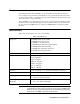
Overview This manual describes the 65-2340RK toxic gas transmitter. This manual also describes how to install, start up, maintain, and calibrate the toxic gas transmitter when used with a gas monitoring controller. A parts list at the end of this manual lists replacement parts and accessories for the toxic gas transmitter. The 65-2340RK toxic gas transmitter can be used for various target gases which are listed in Table 1 below.
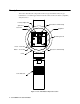
Description This section describes the components of the toxic gas transmitter. The toxic gas transmitter is a 4 - 20 mA type detector head. It consists of the toxic detector, amplifier, and junction box.
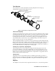
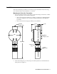
Toxic Detector The toxic detector consists of the detector housing body, detector housing cap, splashguard, cap gasket, and the plug-in sensor. Detector Housing Body (different for each detector type) Cap Gasket Sensor (different for each detector type) Detector Housing Cap Splash Guard (removable) Figure 2: Toxic Detector Component Location Detector Housing Body The detector housing body protects the electronic components within the housing.
corresponds to the detection range and transmits the signal to a gas monitoring controller. A foam gasket that orients the amplifier and keeps it from rotating is installed on the bottom of the amplifier. The amplifier includes the detector terminal strip, controller terminal strip, zero pot, span pot, and test points (see Figure 1). Controller Terminal Strip The controller terminal strip is a two position plug-in style terminal strip located at the top edge of the amplifier.
Installation This section describes procedures to mount the toxic gas transmitter in the monitoring environment and wire the transmitter to a controller. Mounting the Toxic Gas Transmitter 1. Select a mounting site that is representative of the monitoring environment. Consider the following when you select the mounting site. • Select a site where the transmitter is not likely to be bumped or disturbed. Make sure there is sufficient room to perform start-up, maintenance, and calibration procedures.
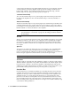
Wiring the Toxic Gas Transmitter to a Controller WARNING: Always verify that power to the controller is off before you make wiring connections. 1. Turn off the controller. 2. Turn off power to the controller. 3. Remove the junction box cover. 4. The detector leads are factory wired. Verify that the detector leads are wired to the amplifier’s detector terminal strip as shown in Figure 4. 5.
+ S Controller D etector/Transm itter Terminals, T ypical Designations Co nt roller H o using Cable Shield OX Y S S IG /PW R Gas T ype T able Gas T ype AsH3 0 - 3 ppm C l2 T O XIC S P AN Z ER O J-Box CL2 0 - 10 ppm Cl2 CL-10 Black + W ire brown yellow y ellow HC N wh ite NH 3 red PH3 green SO2 blue (+) Se e T able Toxic D etector Figure 4: Wiring the Toxic Gas Transmitter to a Controller 12.
Start Up This section describes procedures to start up the toxic gas transmitter and place the transmitter into normal operation. Introducing Incoming Power 1. Complete the installation procedures described earlier in this manual. 2. Verify that the power wiring to the controller is correct and secure. Refer to the controller operator’s manual. 3. Turn on power to the controller. 4. Turn on the controller. 5. Verify that the controller is on and operating properly.
Maintenance This section describes maintenance procedures. It includes preventive maintenance, troubleshooting, and component replacement procedures. Preventive Maintenance This section describes a preventive maintenance schedule to ensure the optimum performance of the toxic gas transmitter. It includes daily, monthly, and quarterly procedures. Daily Verify a display reading of 0 ppm at the controller. Investigate significant changes in the display reading.
9. Use the sample tubing to connect the regulator to the calibration cup. Check the bottom of the calibration cup to see if it has a specified flow direction through the cup and if it does, make sure you connect the tube from the regulator to the inlet port. The 81-1138RK calibration cup, which is used for all detectors except for Cl2 and NH3 detectors, has a specified flow direction on the bottom of the cup. The 81-1138RK-CL2 and 81-1138RK-NH3 calibration cups do not have a specified flow direction. 10.
Table 2:Troubleshooting the Toxic Gas Transmitter Condition Symptom(s) Probable Causes Recommended Action Fail Condition • Controller indicates a fail condition. • The transmitter wiring is disconnected or misconnected. • The plug-in sensor is not properly plugged into the socket in the detector housing body. • The transmitter’s zero reading is low enough to cause a fail condition. • The transmitter is malfunctioning. 1. Verify that the transmitter wiring is correct and secure. 2.
4. Unplug and remove the toxic sensor. 5. Carefully plug the replacement sensor into the connector that is located in the detector housing body. WARNING: You must replace the plug-in sensor with the same type of sensor that is installed. A detector cannot be converted from one type of detector to another by using a different plug-in sensor. For example, if you are replacing a Cl2 sensor, you must replace it with a Cl2 sensor. 6.
Replacing the Amplifier 1. Turn off the controller. 2. Turn off or unplug power to the controller. 3. Remove the junction box cover. 4. Unplug the detector terminal strip and controller terminal strip from their sockets. You may leave the wires connected to the terminal strips. 5. Unscrew and remove the screw with the flat and lock washers that secures the amplifier to the junction box. 6. Remove the old amplifier. 7.
Calibration This section describes how to calibrate the toxic gas transmitter. It includes procedures to prepare for calibration, set the zero (fresh air) reading, set the span (response) reading, and return to normal operation. It describes calibration using a calibration kit that includes a calibration cup, calibration gas, sample tubing, and a fixed flow regulator with an on/off knob. The required sample flow rate and calibration cup depend on the transmitter being calibrated.
For example, with a calibrating sample of .50 ppm and a fullscale setting of 1.00, the correct output is 300 mV. 300(mV) = (.50/1.00) X 400 +100 NOTE: Calibrating the toxic gas transmitter may cause alarms. Be sure to put the controller into its calibration program or disable external alarms before continuing. 6. Unscrew the splashguard from the detector housing cap. Make sure the cap remains securely screwed onto the housing body. 7.
Returning to Normal Operation 1. Remove the voltmeter leads from the amplifier test points. 2. Gently pull the calibration cup off of the plug-in sensor NOTE: For convenience, leave the regulator and calibration cup connected by the sample tubing. 3. Screw the splashguard firmly back onto the housing cap. 4. Secure the junction box cover to the junction box. 5. When the controller display reading falls below the alarm setpoints, return the controller to normal operation.
Table 4: Parts List Part Number Description 81-0076RK-01 Zero air calibration cylinder, 34 liter steel 81-0076RK-03 Zero air calibration cylinder, 103 liter steel 81-0170RK-02 Calibration cylinder, 5 ppm SO2 in nitrogen, 58 liter aluminum 81-0170RK-04 Calibration cylinder, 5 ppm SO2 in nitrogen, 34 liter aluminum 81-0175RK-02 Calibration cylinder, 10 ppm NH3 in nitrogen, 58 liter aluminum 81-0175RK-04 Calibration cylinder, 10 ppm NH3 in nitrogen, 34 liter aluminum 81-0185RK-02 Calibration cyl
Table 4: Parts List Part Number Description 81-F702RK-LV Calibration kit, includes regulator, calibration cup, and a 34 liter 5 ppm SO2 in nitrogen aluminum calibration cylinder 81-F811RK Calibration kit, includes regulator, calibration cup, and a 58 liter 0.5 ppm PH3 in nitrogen aluminum calibration cylinder 81-F811RK-LV Calibration kit, includes regulator, calibration cup, and a 34 liter 0.5 ppm PH3 in nitrogen aluminum calibration cylinder ESM-01DH-ASH3 ESM-01 plug-in sensor, 0 - 1.