
Instruction Manual


65-2330RK H
2
S Transmitter • 15
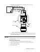
4. Turn the regulator knob clockwise to close the regulator.
5. Unscrew the regulator from the calibration cylinder.
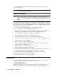
Returning to Normal Operation
1. Remove the voltmeter leads from the amplifier test points.
2. Unscrew the calibration cup from the detector.
NOTE: For convenience, leave the components of the calibration kit connected by the
sample tubing.
3. Secure the junction box cover to the junction box.
4. When the display reading falls below the alarm setpoints, return the controller to
normal operation.
5. Verify that the controller display reading decreases and stabilizes at 0 ppm.
6. Store the components of the calibration kit in a safe and convenient place.
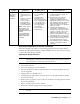
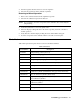
Parts List
Table 5 lists replacement parts and accessories for the H
2
S transmitter.
Table 3: Parts List
Part Number Description
06-1248RK Sample tubing (order by the foot)
07-0033RK Detector housing cap gasket
18-0400RK-01 Junction box with rubber spacers
57-1064RK-03 Amplifier (specify target gas when ordering)
65-2330RK H
2
S transmitter (includes detector and amplifier)
65-2495RK H
2
S replacement detector assembly (includes sensor)
71-0176RK 65-2330RK H
2
S Transmitter Operator’s Manual (this document)
81-0151RK-04 Calibration cylinder (25 PPM H
2
S in nitrogen; 34 liter aluminum)
81-0076RK-01 Zero air calibration cylinder (34 liter steel)
81-1050RK Regulator with gauge and knob, 0.5 LPM, for 17 liter and 34 liter
steel calibration cylinders
81-1051RK Regulator with gauge and knob, 0.5 LPM, for 34AL/58/103 liter
calibration cylinders
81-1117RK Calibration cup
ES-1537-H2S H
2
S replacement sensor