65-2330RK Hydrogen Sulfide Transmitter Operator’s Manual Part Number: 71-0197RK Revision: 0 Released: 4/12/11 RKI Instruments, Inc. www.rkiinstruments.
WARNING Read and understand this instruction manual before operating transmitter. Improper use of the transmitter could result in bodily harm or death. Periodic calibration and maintenance of the transmitter is essential for proper operation and correct readings. Please calibrate and maintain this transmitter regularly! Frequency of calibration depends upon the type of use you have and the sensor types.
Product Warranty RKI Instruments, Inc. warrants gas alarm equipment sold by us to be free from defects in materials, workmanship, and performance for a period of one year from date of shipment from RKI Instruments, Inc. Any parts found defective within that period will be repaired or replaced, at our option, free of charge.
Table of Contents Overview . . . . . . . . . . . . . . . . . . . . . . . . . . . . . . . . . . . . . . . . . . . . . . . . . . . . . . . . . . . . . . . . . . . 1 Specifications. . . . . . . . . . . . . . . . . . . . . . . . . . . . . . . . . . . . . . . . . . . . . . . . . . . . . . . . . . . . . . . . 1 Description . . . . . . . . . . . . . . . . . . . . . . . . . . . . . . . . . . . . . . . . . . . . . . . . . . . . . . . . . . . . . . . . . . 2 H2S Detector . . . . . . . . . . . . . . . . . . . . . . .
Overview This manual describes the 65-2330RK hydrogen sulfide (H2S) transmitter. This manual also describes how to install, start up, maintain, and calibrate the transmitter when using it with a gas monitoring controller. A parts list at the end of this manual lists replacement parts and accessories for the H2S transmitter. See the controller operator’s manual for information specific to the controller. Specifications WARNING: Do not use this product in a manner not specified in this instruction manual.
Description This section describes the components of the H2S transmitter. The H2S transmitter is a 4-20 mA type detector head. It consists of the H2S detector, amplifier, and junction box.
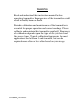
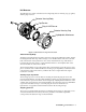
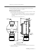
H2S Detector The H2S detector consists of the detector housing body, detector housing cap, cap gasket, and the plug-in sensor. Detector Housing Body Cap Gasket Plug-In H2S Sensor Detector Housing Cap Hydrophobic Membrane Figure 2: H2S Detector Component Location Detector Housing Body The detector housing body protects the electronic components within the housing. Use the mounting threads at the top of the housing to screw the H2S detector into the 3/4” NPT hub on the bottom of the junction box.
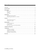
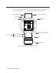
Amplifier The amplifier converts the electrical output from the sensor to a 4 to 20 mA signal that corresponds to the detection range and transmits the signal to a gas monitoring controller. A foam gasket that orients the amplifier and keeps it from rotating is installed on the bottom of the amplifier. The amplifier includes the controller terminal strip, detector terminal strip, zero pot, span pot, and test points (Figure 1).
calibration cup on the detector during calibration. Installation This section describes procedures to mount the H2S transmitter in the monitoring environment and wire the transmitter to a controller. Mounting the H2S Transmitter 1. Select a mounting site that is representative of the monitoring environment. Consider the following when you select the mounting site. • Select a site where the transmitter is not likely to be bumped or disturbed.
Wiring the H2S Transmitter to a Controller WARNING: Always verify that power to the controller is OFF before you make wiring connections. 1. Turn off the controller. 2. Turn off power to the controller. 3. Remove the junction box cover. 4. The detector leads are factory wired. Verify that the detector leads are wired to the amplifier’s detector terminal strip as shown in Figure 4. 5.
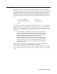
. Connect the wires to the applicable detector/transmitter terminal strip at the controller as shown in Figure 4. 4 - 20 mA In (S) + 24 VDC Cable Shield S SIG/ PWR TOXIC OXY SPAN Z ERO Controller J-Box Black H2S Detector Red Figure 4: Wiring the H2S Transmitter to a Controller 12. If shielded cable is used, connect the cable’s drain wire to an available chassis (earth) ground at the controller. RKI controllers typically have a ground stud that can be used to ground the cable’s drain wire.
5. Verify that the controller is on and operating properly. Refer to the controller operator’s manual. CAUTION: Allow the transmitter to warm up for 5 minutes before you continue with the next section, “Setting the Zero Signal”. Setting the Zero Signal NOTE: If you can verify that the detector is in a fresh air environment (environment known to be of normal oxygen content and free of toxic and combustible gases), it is not necessary to apply zero air when verifying or setting the fresh air reading.
Daily Verify a display reading of 0 ppm H2S at the controller. Investigate significant changes in the display reading. Monthly This procedure describes a test to verify that the H2S transmitter responds properly to hydrogen sulfide. It describes the test using a calibration kit that includes a calibration cup, calibration gas, sample tubing, and a fixed flow regulator with an on/off knob. NOTE: Performing a response test on the H2S transmitter may cause alarms.
7. Reinstall the junction box cover. 8. When the controller display reading falls below the alarm setpoints, return the controller to normal operation. 9. Store the components of the calibration kit in a safe place. Quarterly Calibrate the H2S transmitter as described in “Calibration” on page 13. See the calibration frequency discussion in “Calibration Frequency” on page 13 to determine if a quarterly calibration schedule fits your needs.
Condition Slow or No Response/ Difficult or Unable to Calibrate Symptom(s) Probable Causes Recommended Action • Transmitter responds slowly or does not respond to response test. • Unable to accurately set the zero or response reading during calibration. • Transmitter requires frequent calibration. • The calibration cylinder is low, out-dated, or defective. • The hydrophobic membrane in the detector housing cap is wet or clogged with dirt or other particulates.
9. Calibrate the transmitter as described in “Calibration” on page 13. Replacing the H2S Detector NOTE: In most cases, it is only necessary to replace the plug-in H2S sensor. 1. Turn off the controller. 2. Turn off or unplug power to the controller. 3. Remove the junction box cover. 4. Remove the detector terminal strip from its socket. 5. Disconnect the detector leads from the detector terminal strip. Note the position of the color-coded leads as you remove them. 6.
Replacing the Amplifier 1. Turn off the controller. 2. Turn off or unplug power to the controller. 3. Remove the junction box cover. 4. Unplug the detector terminal strip and controller terminal strip from their sockets. You may leave the wires connected to the terminal strips. 5. Unscrew and remove the screw with the flat and lock washers that secures the amplifier to the junction box. The screw is at the bottom right of the amplifier. 6. Remove the old amplifier. 7.
Instruments, Inc. recommends using a 0.5 LPM (liters per minute) fixed flow regulator. Preparing for Calibration NOTE: Calibrating the H2S transmitter may cause alarms. Be sure to put the controller into its calibration program or disable external alarms before calibration. WARNING: Do not remove the detector housing cap or junction box cover while the circuits are energized unless the area is determined to be non-hazardous.
4. Turn the regulator knob clockwise to close the regulator. 5. Unscrew the regulator from the calibration cylinder. Returning to Normal Operation 1. Remove the voltmeter leads from the amplifier test points. 2. Unscrew the calibration cup from the detector. NOTE: For convenience, leave the components of the calibration kit connected by the sample tubing. 3. Secure the junction box cover to the junction box. 4.