
Manual


49-8104RK Standby Battery • 13
9. Carefully remove the battery bracket and batteries from the case.
10. Replace the batteries in the bracket with the new batteries.
NOTE: Dispose of the old batteries properly.
11. Place the battery bracket with the batteries in the case and line up the mounting holes
in the bracket with the mounting holes in the case. Hold the bracket with the batteries
in place firmly.
12. Install the bottom screws that retain the battery bracket and tighten firmly.
13. Install the top screws that retain the battery bracket and tighten firmly.
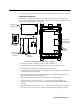
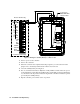
14. Install the positive and negative connections to the appropriate battery terminals (see
Figure 4, Figure 6, and Figure 6).
15. Turn on power to the controller.
16. Turn on the controller.
17. When the controller has completed its warm-up sequence, install the jumper wire
between the two batteries (see Figure 4, Figure 6, and Figure 6).
18. Close the standby battery housing door.
19. The on/off switch in the Beacon 200, Beacon 410, and Beacon 800 controls AC power
to the instruments. Verify that the standby battery is installed properly by flipping the
on/off switch to the off position and observing that the controller continues to operate
powered by the standby battery.
20. Flip the on/off switch to the on position.
Parts List
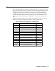
Table 3 below lists spare parts for the standby battery.
Table 3: Standby Battery Spare Parts
Part Number Description
18-0107RK 3/4” NPT conduit hub
18-0112RK Vent
45-0600RK Wire nut, for 22 - 14 AWG wire
49-1552RK Battery, lead acid, 12 V, 12 amp hour