49-8104RK Standby Battery Operator’s Manual Part Number: 71-0118RK Revision: B Released: 2/19/13 www.rkiinstruments.
Product Warranty RKI Instruments, Inc. warrants gas alarm equipment sold by us to be free from defects in materials, workmanship, and performance for a period of one year from date of shipment from RKI Instruments, Inc. Any parts found defective within that period will be repaired or replaced, at our option, free of charge.
Overview This manual describes the 49-8104RK standby battery. This manual also describes how to install and maintain the standby battery. Specifications Table 1 lists specifications for the standby battery. Table 1: Specifications Construction (housing) Weatherproof ABS plastic Power Rating 24 VDC, 12 AH (amp hour) Operating Temperature 32° F to 104° F (0°C to 40°C) Size 11.28” H x 7.48” W x 5.
Housing The standby battery’s fiberglass housing is weather- and corrosion-resistant. It is suitable for installation where general purpose equipment is in use. The housing door is hinged on the left side and is secured by two latches on the right side. Four mounting feet are attached to the back of the housing (one at each corner). The mounting feet allow you to install the housing to a vertical surface. A conduit hub on the top of the housing is for external wiring connections.
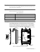
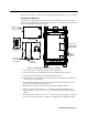
Installation This section describes procedures to mount the standby battery and wire it to a controller. Installing the Batteries The batteries are shipped separately in order to prevent damage to the housing. Three wires are provided in a bag in order to make connections to the batteries. The figure below shows how the standby battery is shipped.
CAUTION: Before continuing, confirm that the positive wire (red) and the negative wire (black) are not shorting to each other. Each wire has shrink tubing on the end to prevent shorting. Leave the shrink tubing on. 9. Install the wire jumper between the “+” connection of the top battery and the “-” connection of the bottom battery (see Figure 1). This wire is one of three wires in a small bag included with the shipping contents. Mounting the Standby Battery 1.
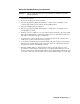
Wiring the Standby Battery to a Controller WARNING: Always verify that all power to the controller is OFF before you make wiring connections. 1. Turn off the controller. 2. Turn off or unplug power to the controller. 3. Install an appropriately rated cable bushing or conduit to the conduit hub on the controller that will be used for wires from the standby battery. 4. Open the standby battery housing door. 5.
10. Use the wire nuts provided with the standby battery to connect the positive and negative wires in the standby battery to the positive and negative wires coming from the controller as shown in Figure 4, Figure 5, and Figure 6.
Connections Made With Wire Nuts Provided Beacon 410 Housing Controller Terminal Strip User Installed Jumper Standby Battery Shown Without Door Figure 5: Wiring the Standby Battery to a Beacon 410 49-8104RK Standby Battery • 9
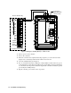
Connections Made With Wire Nuts Provided FAIL ALM1 ALM2 24 VDC Beacon 800 Housing BAT BAT+ C NO NC C NO NC C NO NC +28V TX RX GND User Installed Jumper RESET RESET BUZ BUZ + Controller Terminal Strip Standby Battery Shown Without Door Figure 6: Wiring the Standby Battery to a Beacon 800 11. Turn on power to the controller. 12. Turn on the controller. 13. When the controller has completed its startup sequence, re-connect the end of the jumper wire to the battery terminal from which it was removed.
Operation When the standby battery is connected to an RKI Instruments, Inc. controller such as the Beacon 200, Beacon 410, or the Beacon 800, the controller maintains a trickle charge on the battery to keep it fully charged. If primary AC power to the controller goes down, the standby battery will power the controller for a limited amount of time until primary power returns. When primary AC power returns, the controller will begin charging the standby battery.
Maintenance This section describes preventive maintenance and troubleshooting procedures. It also includes component replacement procedures and a parts list. Preventive Maintenance Check the standby battery voltage with a volt meter on a quarterly basis and verify that it is fully charged. A fully charged standby battery connected to a controller that trickle charges it will typically measure between 28 volts and 29 volts.
9. Carefully remove the battery bracket and batteries from the case. 10. Replace the batteries in the bracket with the new batteries. NOTE: Dispose of the old batteries properly. 11. Place the battery bracket with the batteries in the case and line up the mounting holes in the bracket with the mounting holes in the case. Hold the bracket with the batteries in place firmly. 12. Install the bottom screws that retain the battery bracket and tighten firmly. 13.