
User Manual


4 • 35-3010RKA-06 Sample-Draw Detector
Charcoal Filter
The charcoal filter is locat ed in the top left corner of the enclosure. It is he ld in place by a
metal clip. The charcoal filter is placed aft er the H
2
S sensor and before the CO sensor ( if
one is installed) in th e flow system. It scrubs out interfering ga ses which may cause the
CO sensor to respond, such as H
2
S or certain hydrocarbons. It is included in this version
of the sample draw detector in case a CO sensor is added in the field. If a CO sensor is
added in the field, a new charcoal filter should also be installed.
Pump
The pump is located to the lef t of the main circuit board near the bottom left of the
sample-draw detector. The pump pulls the gas sample into the sample-draw detector. The
pump operates on 24 VAC, which is generated from the 24 VDC supplied to the sample
draw detector.
Flowmeter
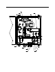
The flowmeter is attach ed to the main circuit board n ear the top left corner (see Figure 4).
A ball in the flowmeter column indica tes the flow rate to the sensors. The flow meter
measures the flow in the range 0.2 to 2.0 SCFH (Standard Cubic Feet per Hour). Although
the sample-draw detector will operate down to a flow of 0.6 SCFH, the optimum flow rate
is 1.2 SCFH.
Bypass Valve
The bypass valve is to the left of the flowmeter. The bypass valve adjusts the flow rate to
the senso r s. Use a flat-bl ade screwdriver to adjust the bypass v alve.
NOTE: The bypass valve allows fine adjustments of the flow rate. For a wider range of
adjustment, use the flow adjust potentiometer (see Figure 4).
Status Lights
Two status lights are above the flowmeter.
Pilot Light
The green Pilot light is on when the sample-draw detector is receiving power.
Fail Light
The red Fail light is on when the sample flow rate is below the low flow level.
NOTE: The factory set low flo w level is 0.6 SCFH (±0.2). See “A d justing the Low Flow
Setting” on page 18 for instructions to adjust this setting.
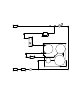
Pressure Switch
The pressure switch is moun ted to the opposite side of the main circuit board. The
pressure switch monitors the flow rate to the sensors.
If the flow rate falls below the preset low flow level, the pressure switch causes the fail
relay to interrupt the signal in the 4-20 mA line for the H
2
S channel. This causes a
downscale reading at the monitor on this channel. The low flow level is f acto r y- set at 0.6
SCFH (±0.2 SCFH).
NOTE: There is no low flow indication for the LEL channel.