
User Manual


35-3010RKA-06 Sample-Draw Detector • 3
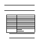
An aluminum subpanel is mounted to the interior of the housing. The sam ple-draw
detector’s internal components are mounted to the subpanel.
Flow System
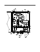
The sample-draw detector’s flow system consists of the INLET fitting, hydrophobic filter,
charcoal filter, pump, flowmeter, bypass valve, status lights, pressure switch, flow block,
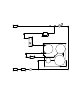
and EXHAUST fitting (see Figure 1). Figure 2 illustrates how the gas sample moves
through the flow system.
Figure 2: Sa mple-Draw Detector Flow Diagram
INL E T Fitt in g
The INLET fitting on the bottom of the housing allows the gas sample to enter the sample-
draw detector. The INLET fitting accepts 1/4 in. rigid tubing. See “Installation” on page 9
for instructions to co nnect tubing to the INLET fitting.
Hydrophobic Filter
The hydrophobic filter is to the left of the main circuit board. It is held in place by a metal
clip. It prevents water and other liquids from contaminating the flow system. Replace the
filter when it appears dirty, discolored, or clogged. If a liquid other than wa ter is drawn
into the filter, replace the filter as soon as possible.
Oxygen
Dum my
Plug
Hydrophobic
Filter
Inlet
Exhaust
Pump
CO
Dum my
Plu g
Flow m eter
Flow B lock
Bypass
Valve
H2S
Pre ssure Switc h
Charcoal
Filter
LEL