
User Manual


20 • 35-3010RKA-06 Sample-Draw Detector
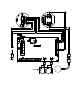
7. Disconnect th e sample tubing from the inlet line.
8. Unscrew the regulator from the zero air calibration cylinder. Leave the sample tubing
connected to the regulator.
Setting the Response Reading
1. Screw the regulator into the 4-gas calibration cylin der.
2. Connect the sample tubing from the regulator to the inlet line at or nea r the sample-
draw detector’s INLET fitting.
3. Allow the ca libration gas to flow for one minute.
4. Check the mV output on the LEL transmitter test points and verify that the reading
matches the response reading (±2 mV) you determined earlier.
5. If necess ary, use the span pot on the LEL transmitter to adjust the r eading to match the
correct response reading.
6. Repeat steps 3 a nd 4 for th e H
2
S channel using the appropriate test points described in
the Preparing For Calibration section above and the appropriate span pot.
7. Disconnect the samp le tubing from the sample-draw detector’s inlet line.
8. Unscrew the regulator from the calibration cylinder.
NOTE: For convenience, leave the regulator connected to the sample tubing.
Returning to Normal Operation
1. Remove the voltmeter leads from the test points.
2. Reconn ect the incoming sample line.
3. Wait 1 to 2 minutes to allow the calibration ga s to be drawn out and the readings to
stabilize.
4. Close the housing door.
5. Store t he c omponents of the calib ration kit in a safe and co nvenient place.