
User Manual


35-3010RKA-06 Sample-Draw Detector • 15
Monthly
This proc edure describ e s a test to verify that the sample-draw detector responds properly
to the target gases.
Prepari ng for the respon se test
CAUTION: This proce dure may cause alarms at the controller. Take appropriate action to avoid
this, such as entering the calibration mode at the controller or disabling external
alarms.
1. Verify that the controller is reading 0 for the combustible and H
2
S channels.
If the reading is not 0 on th e combustible or H
2
S channels, set the zero reading as
described in “Start Up” on page 13, then continue this procedure.
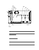
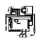
2. Assemble the calibration kit as described in “P reparing fo r Calibration” on page 19.
Use of a 4-gas cylinder is recommend e d so that all channels may be checked at once.
Performing the response test
NOTE: This procedure describes the RKI calibration kit that includes a demand flow
regulator. A calibratio n kit that uses a calibration bag is also available.
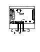
1. Screw the regulator into the calibration cylinder.
2. Co nn ect th e ca lib rati on tub ing from the r e gul ator to the inlet line at or near the INLET
fitting. Gas will begin to flo w.
3. After approximately one minute, verify that the reading for each channel at the
controller stabilizes within ± 20% of the concentration of the test sample . If the
reading is not within ± 20% o f the test sample, calibrate the sample-draw detector as
described in “Calibration” on page 19.
4. Remove the calibration tubing from the inlet lin e, then reconnect the inlet line.
5. Store the calibration kit in a safe place .
Quarterly
Calibrate t he sample-draw detector as described in “Calibration” on page 19.
Troubleshooting
The troubleshooting guide describes symptoms, probable causes, and recommended
action for problems you may encounter with the sample-draw gas detector.
NOTE: This troubleshooting guid e describes sample-draw detector problems only. See
the instruction manual for the controller if it exhibits any problems.
Fail Condition
Symptoms
• The sample-dra w d e tector’s Fa il light is on .
• The controller is operating properly but indicates a reading well below zero on one or
more channels.
Probable C aus es
• The sample-draw detector’s flow rate is too low because of an obstructed sample line,