
User Manual


35-3010RKA-06 Sample-Draw Detector • 13
Start Up
This section describes procedures to start up the sample-draw detector and place the
sample-draw detector into n ormal operation.
Introducing Incoming Power
1. Complete the install ati on procedures described earlier in this manual.
2. Verify that the power wiring to the controller is correct and secure. See the controller
operator’s manual .
3. Turn on or plug in the incomin g power at the controller, then turn on the con troller.
4. Ve rify that the controller is on and operating properly.
5. Verify tha t the Pilot light is on at the sa mple draw detector.
6. Verify that the flowmeter indicates a flow rate of approximately 1.2 SCFH. If
necessary, use the bypass valve or flow adj ust potentiom eter to adjust the fl ow rate.
NOTE: The following step tests for leaks in the sample line. This tes t ma y cause a low
flow condition at the sample-draw detector.
7. Verify that the incoming sampl e line is not leaking. To test the sample line, plug th e
open end of the sample line with your thumb. If the flowmeter ball drops to the
bottom of the f lowmeter, the incoming sample line is not lea king.
8. Remove your thumb from the sample line, press the pump re set switch, and verify the
flowmeter returns to a normal flow rate.
Setting the Zero Reading
CAUTION: If you suspect the presence of combustible gas, hydrogen sulfide, or an abnormal
oxyge n cond ition ( not 20.9 %) in the monit oring e nvir onmen t, use th e calib ration kit
and th e z ero air calibrati on cylinder to int rodu ce “fresh air” to the sa mple d ra w
adapter and verify an accurate zero setting.
1. Verify that the sample-draw detector is sampling a fresh air environment
(environment known to be free of combustible gas, H
2
S and of normal oxygen
content, 20.9%).
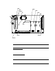
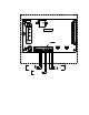
2. Open the housing door.
3. Set a voltmeter to measure in the millivolt (mV) range.
4. Check the zero reading for each channel.
For the LEL chan nel, plug the voltmeter leads into the test points on the LEL
transmitter. Plug the positive lead into the test point labeled TP+; plug the negative
lead into the test point labeled TP-.
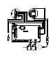
For the H
2
S channel, plug the voltmeter into the test points in the AMP 2 section of the
main circuit board. Plug the positive lead into the test point labeled CAL+2; plug the
negative lead in to the test point labeled CAL-2.
5. Verify a volt meter readin g of 100 mV (± 2 mV).
6. If necessary, use a small flat-blade screwdriver to adjust the zero pot until the
voltmeter reading is 100 mV (± 2 mV).
7. Close the housing door.