
User Manual


35-3010RKA-06 Sample-Draw Detector • 7
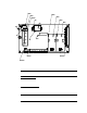
Main Circuit Board
Figure 4: Main Circuit Board
The main circuit board includes th e interconnect terminal strip, sensor/transmitter
terminal strip, amp 1 circuit, amp 2 circuit, pump terminal strip, relay, and reset switch.
NOTE: The flowmeter and status lights are mounted to the main circuit board but are
considered part of the flow system.
Interconnect Terminal Strip
The interconnect terminal strip is the sixteen-point terminal strip near the bo ttom edge of
the main circuit board. Use the interco nn e ct termin al strip to connect the samp le-draw
detector to a controller.
Sensor/Transmitter Terminal Strip
The sensor/transmitter terminal strip is the sixteen-point terminal strip nea r the right
edge of the circuit board. Use the transmitter terminal strip to connect sensors or
transmitters to the m ai n circuit board.
NOTE: The sensors and transmitters are factory wired to the sensor/transmitter
terminal strip. See “Wiring the Sample- Dra w Detector” on page 10 fo r all wiring
procedures related to the sample-draw detector.
Test Poi nt CAL +
2
Amp 1
(CO )
Zero Span Zero
Fail LED
Sensor/Trans mitter
Terminal Strip
Press ure Switch
Reset
Switch
Pilo t LED
Amp 2
(H2S)
Span
Test Point CAL + 1
Test Point CAL - 2
Test Poi nt CAL - 1
AC Terminal
Strip Not Used
Interco nnect Terminal
Stri p
Low Flow Adjust
Flow Adjust P ot
Flowmeter
P um p Te rm inal St ip
Relay