
Owner's manual

14 • 35-3010RKA-03 Sample-Draw Detector
Start Up
This section describes procedures to start up the sample-draw detector and place the
sample-draw detector into normal operation.
Introducing Incoming Power
1. Complete the installation procedures described earlier in this manual.
2. Verify that the power wiring to the controller is correct and secure. See the controller
operator’s manual.
3. Turn on or plug in the incoming power at the controller, then turn on the controller.
4. Verify that the controller is on and operating properly.
5. Verify that the Pilot light is on at the sample draw detector.
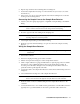
6. Verify that the flowmeter indicates a flow rate of approximately 1.2 SCFH. If
necessary, use the bypass valve or flow adjust potentiometer to adjust the flow rate.
NOTE: The following step tests for leaks in the sample line. This test may cause a low
flow condition at the sample-draw detector.
7. Verify that the incoming sample line is not leaking. To test the sample line, plug the
open end of the sample line with your thumb. If the flowmeter ball drops to the
bottom of the flowmeter, the incoming sample line is not leaking.
8. Remove your thumb from the sample line, press the pump reset switch, and verify the
flowmeter returns to a normal flow rate.
Setting the Zero Reading
CAUTION: If you suspect the presence of combustible gas, carbon monoxide, or an abnormal
oxygen condition (not 20.9%) in the monitoring environment, use the calibration kit
and the zero air calibration cylinder to introduce “fresh air” to the sample draw
adapter and verify an accurate zero setting.
1. Verify that the sample-draw detector is sampling a fresh air environment
(environment known to be free of combustible gas, CO, and of normal oxygen
content, 20.9%).
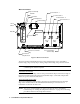
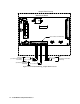
2. Open the housing door.
3. Set a voltmeter to measure in the millivolt (mV) range.
4. Check the zero reading for each channel.
For the LEL channel, plug the voltmeter leads into the test points on the LEL
transmitter. Plug the positive lead into the test point labeled TP+; plug the negative
lead into the test point labeled TP-.
For the oxygen channel, plug the voltmeter into the test points on the oxygen
transmitter. Plug the positive lead into the test point labeled TP+; plug the negative
lead into the test point labeled TP-.
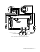
For the CO channel, plug the voltmeter into the test points in the AMP 1 section of the
main circuit board. Plug the positive lead into the test point labeled CAL+1; plug the
negative lead into the test point labeled CAL-1.
5. Verify a voltmeter reading of 100 mV (± 2 mV).