
User Manual


35-3010RKA-02 Sample-Draw Detector • 5
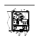
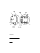
Flow Block
The flow block is lo cated in the lower right corner of the sample-draw detector. All the
sensors are installed in the flow block. The flow block routes the sampled air to each
sensor.
EXHAUST Fitting
The EXHAUST fitti ng on the bottom of the housing allows the gas samp le to exit the
sample-draw detector. The EXHAUST fitting accepts 1/4 in. rigid tubing. See
“Installation” on page 10 for instructions to connect tubing to the EXHAUST fitting.
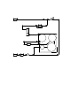
Detection System
The detection system consists of the gas sensors, LEL and oxygen transmitters, preamp
circuit board, and the main circuit board.
Combustible Gas Sensor
The combustible gas sensor is installed in the lower left of the flow block. The combustible
gas sensor includes the sensing elements, flame arrestor, connector, and sensor leads.
Sensing Elements
Two sensing elements are protected within the sensor assembly. Through a series of
thermal and electro nic r eactions, these e lements produce an output that is propor tional to
the detection range of the sample draw detector. The LEL transmitter converts the output
to a 4 - 20 mA signal w hich can be used by a recording or monito ri ng d evice.
The porous flame arr es tor allows the gas sample to enter the sensor assembly and contact
the sensing element. The flame arrestor also contains sparks within the sensor.
Connector
The top of the sensor includes five pins that plug into the socket connector . This connector
allows you to replace the sensor without disconnecting the wiring. The sensor leads are
soldered to the connector.
Sensor Leads
Four color-coded leads extend from the connector. The leads allow you to connect the
combustible ga s sensor to the main circuit board.
Oxygen Sensor
The oxygen sensor is installed in the lower right of the flow block. The oxygen sensor
includes the oxygen cell, connector, and sensor leads .
Oxygen Cell
The oxygen cell is protected within the sensor assembly. Through a series of chemical and
electronic reactions, the cell produces a mil livolt output that is proportional to the
detection range of the sample-d raw detector. The oxygen transmitter converts the output
to a 4 - 20 mA signal w hich can be used by a recording or monito ri ng d evice.
Connector
The cable that extends from the sensor terminates in a socket that plugs into a matching
7-pin male connector. The socket and connector allow you to replace the sensor without
disconnecting the wiring. The sensor leads are soldered to the male connector.
Sensor Leads
Two color-coded leads extend fro m th e connecto r. The leads allow you to connect the
oxygen sensor to the m ain circuit board.