
User Manual


35-3010RKA-02 Sample-Draw Detector • 11
5. Repeat steps 3 and 4 for the remaining three mounting feet.
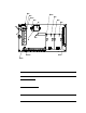
6. Posit ion the samp le-dr aw hou sing o n a vertical surf ace at eye level (4 1/2 to 5 feet
from the floor).
7. Insert 1/4 in. or 5/16 in. sc rews t h rou g h the slots in the m o unting f eet t o secure the
housing to the mounting surf ace.
Connecting the Sample Lines to the Sample-Draw Detector
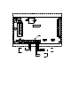
1. Attach 1/4 in. O.D. rigid polypropylene or rigid Teflon sample tubing to the INLET
fitting.
CAUTION: If you use flexible sample tubing (polyurethane is acceptable), use an appropriate
insert t o seal the conne ction between the t u bing an d the INLET fitting.
2. Place the opposite end of the tubing at the sampling area.
CAUTION: A void loops or slumps in the incoming sample line. To reduce response time, keep the
incoming sample line as short as possible.
3. Attach rigid sample tubing to the EXHAUST f itting.
4. Route the opposite end of the tubing to an open area where the sample can safely
disperse.
Wiring the Sample-Draw Detector
WARNING : Always veri f y that the power source is OFF before you make wi ring
connections.
1. Tu rn off t he contro ller.
2. Turn off or unplug incoming power to the controller.
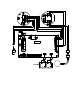
3. Unlatch an d op en the housing door of the sample- d raw detector.
4. Guide a eight-conductor 18 g auge, shielded cable or eight 18 gauge wires in conduit
through one of the conduit hubs at the bottom of the sample-draw housing. If
necessary, use both hubs to bring the wires in ma king sure that all the wires for a
particular channel go through the same hub.
5. Connect the cable to the sample-draw detector’s interconnect terminal strip as shown
in Figure 6.
6. Close and latch the housing door of the sample-draw detect or.
CAUTION: Leave the cable shield drain wi re insulated and disconnected at the sample-draw
detector. Yo u will connect the o pposit e end of t he drain wire at the co ntroller.
7. Route the cable or wires in conduit leading from the sample-draw detecto r to the
controller.
8. Connect the drain wir e to an available chassis groun d at the controller. RKI controllers
typically have a ground stud that can be used to ground the cable’ s drain wire.