
User Manual


35-3010RKA-02 Sample-Draw Detector • 9
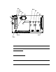
Amp 1 and Amp 2 Circuits
These circuits are located to the left of the sensor/transmitter terminal strip. They each
include test points, a zero pot, and a span pot. Amp 1 is on the left and is for the CO
channel. Amp 2 is on the right and is for the H
2
S channel.
The zer o and span po ts are used durin g ca librati on. Use the s pan pot to make adj ustment s
to gas response readings and the zero pot to make adjustme nts to the zero reading.
The test points are labeled CAL-1 and CAL+1 for the CO channel and CAL-2 and CAL+2
for the H
2
S channel. A 100 mV - 500 mV output is available at the H
2
S test points for use
during calibration. No output is available at the CO test poin ts.
Pump Terminal Strip
The pump terminal strip is the four-point terminal in the top left corner of the circuit
board. Use the pump terminal strip to con nect th e pu mp a nd pressure switch to the main
circuit board.
NOTE: The pump and pressure switch are factory-wired to the circui t board. See
“W iring the Sample-Draw Detector” on page 11 for all wiring procedures r elated
to the sample-draw detector.
Relay
The relay is approximately in the middle of the circuit board. The relay is a four pole,
double-throw (4PDT) relay and is rated for 2 amps at 25 VDC (resistive). If the pressure
switch senses a low flow condition, the relay interrupts the 4-20 mA signal from the H
2
S
channel which will cause a downscale reading at the cont roller or recording device.
NOTE: There is no flow fail indication for the LEL and oxygen channels on the
35-3010RKA-02 Sample Draw Adapter.
Reset S witch
A small reset button is located in the upper left corner of the main PCB. When a low flow
condition occurs, the pump wil l be shut off. To reset the low flow con dition and star t the
pump again, press and hold the reset switch for about 2 se conds, th en release.