
User Manual


8 • 35-3010RKA-02 Sample-Draw Detector
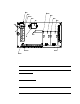
Main Circuit Board
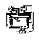
Figure 4 : Main Circuit Board
The main circuit board includes th e interconnect terminal strip, sensor/transmitter
terminal strip, amp 1 circuit, amp 2 circuit, pump terminal strip, relay, and reset switch
(see Figure 4).
NOTE: The flowmeter and status lights are mounted to the main circuit board but are
considered part of the flow system.
Interconnect Terminal Strip
The interconnect terminal strip is the sixteen-point terminal strip near the bo ttom edge of
the main circuit board. Use the interco nn e ct termin al strip to connect the samp le-draw
detector to power and an external device.
Sensor/Transmitter Terminal Strip
The sensor/transmitter terminal strip is the sixteen-point terminal strip nea r the right
edge of the circuit board. Use the transmitter terminal strip to connect sensors or
transmitters to the m ai n circuit board.
NOTE: The sensors and transmitters are factory wired to the sensor/transmitter
terminal strip. See “Wiring the Sample-Draw Detector” on page 11 for all wiring
procedures related to the sample-draw detector.
Test Point CAL + 2
Amp 1
(CO)
Zero Span Zero
Fail LED
Sensor/Trans mitter
Terminal Strip
Pressure Switch
Reset
Switc h
Pilo t LED
Amp 2
(H2S)
Span
Test Point CAL + 1
Test Point C AL - 2
Test Point CAL - 1
AC Te rminal
Strip Not Used
Interconnect Terminal
Strip
Low Flow Adjust
Flow Adjust Pot
Flowm eter
P ump Term in al St ip
Relay