
Manual

35-3010RKA-01 Sample-Draw Detector • 25
response reading.
8. Disconnect the sample tubing from the sample draw detector’s inlet line.
9. Unscrew the regulator from the calibration cylinder.
NOTE: For convenience, leave the regulator connected to the sample tubing.
Returning to Normal Operation
1. Remove the voltmeter leads from the test points.
2. Reconnect the incoming sample line.
3. Wait 1 to 2 minutes to allow the calibration gas to be drawn out and the readings to
stabilize.
4. Close the housing door.
5. Store the components of the calibration kit in a safe and convenient place.
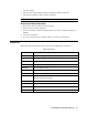
Parts List
Table 4 lists replacement parts and accessories for the sample-draw gas detector.
Table 2: Parts List
Part Number Description
06-1248RK Sample tubing, 3/16 x 5/16, specify length, (for calibration kit)
07-0034RK Sealing gasket, for CO and H
2
S flow block cavities
30-0610RK Pump
33-0171RK Hydrophobic filter (AcroPak)
33-6095RK Charcoal filter, CF-188
65-0601RK Oxygen sensor
81-0076RK-01 Zero air calibration cylinder (34 liter)
81-0154RK-04 4-gas calibration gas cylinder, 50% LEL methane/12% oxygen/25
ppm H
2
S/50 ppm CO, 34 liter
81-1055RK Regulator, demand flow, for 17 and 34 liter steel cylinders
ES-1531-CO CO sensor
ES-1537-H2S H
2
S sensor
NC-6245 Combustible sensor