35-3010RK-06-02 Sample-Draw Detector Part Number: 71-0203RK Revision: B Released: 9/10/12 rkiinstruments.
WARNING Read and understand this instruction manual before operating detector. Improper use of the detector could result in bodily harm or death. Periodic calibration and maintenance of the detector is essential for proper operation and correct readings. Please calibrate and maintain this detector regularly! Frequency of calibration depends upon the type of use you have and the sensor types.
Product Warranty RKI Instruments, Inc. warrants gas alarm equipment sold by us to be free from defects in materials, workmanship, and performance for a period of one year from date of shipment from RKI Instruments, Inc. Any parts found defective within that period will be repaired or replaced, at our option, free of charge.
Table of Contents Overview . . . . . . . . . . . . . . . . . . . . . . . . . . . . . . . . . . . . . . . . . . . . . . . . . . . . . . . . . . . . . . . . . . . 1 Specifications. . . . . . . . . . . . . . . . . . . . . . . . . . . . . . . . . . . . . . . . . . . . . . . . . . . . . . . . . . . . . . . . 1 Description . . . . . . . . . . . . . . . . . . . . . . . . . . . . . . . . . . . . . . . . . . . . . . . . . . . . . . . . . . . . . . . . . . 2 Housing . . . . . . . . . . . . . . . . . . . . . . . . . .
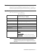
Overview This manual describes the 35-3010RK-06-02 sample-draw detector. This manual also describes how to install, start up, maintain, and calibrate the detector. A parts list at the end of this manual lists replacement parts and accessories for the sample-draw detector. Specifications Table 1 lists specifications for the 35-3010RK-06-02.
Description This section describes the components of the 35-3010RK-06-02 sample-draw detector. The sample-draw detector consists of the housing, flow system, and detection system.
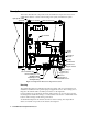
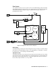
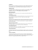
Flow System The sample-draw detector’s flow system consists of the INLET fitting, hydrophobic filter, charcoal filter, pump, flowmeter, bypass valve, status lights, pressure switch, flow blocks, and EXHAUST fitting (see Figure 1). Figure 2 illustrates how the gas sample moves through the flow system.
Charcoal Filter The charcoal filter is located above the main PC board. It is held in place by a metal clip. The charcoal filter is placed before the CO sensor in the flow system. It scrubs out interfering gases which may cause the CO sensor to respond, such as H2S or certain hydrocarbons. Replace the charcoal filter when false high CO readings are noticed, especially in the presence of H2S. Pump The pump is located to the left of the main circuit board near the bottom left of the sample-draw detector.
Flow Blocks Both flow blocks are located in the lower right corner of the sample-draw detector. The oxygen and CO sensors are installed in the larger flow block. The smaller flow block houses the IR CO2 sensor. The flow blocks route the sampled air to each sensor. EXHAUST Fitting The EXHAUST fitting on the bottom of the housing allows the gas sample to exit the sample-draw detector. The EXHAUST fitting accepts 1/4 in. rigid tubing. See “Installation” on page 8 to connect tubing to the EXHAUST fitting.
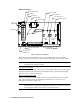
Main Circuit Board Pump Terminal Stip Test Point CAL - 1 Fail LED Test Point CAL + 1 Flowmeter Test Point CAL - 2 Flow Adjust Pot Test Point CAL + 2 Low Flow Adjust Reset Switch Pilot LED Relay Pressure Switch Zero Span Amp 1 (CO) Interconnect Terminal Strip Zero Span Amp 2 (H2S) Sensor/Transmitter Terminal Strip AC Terminal Strip Not Used Figure 3: Main Circuit Board The main circuit board includes the interconnect terminal strip, sensor/transmitter terminal strip, amp 1 circuit, amp 2 cir
Amp 1 and Amp 2 Circuits These circuits are located to the left of the sensor/transmitter terminal strip. They each include test points, a zero pot, and a span pot. Amp 1 is on the left and is for the CO channel. Amp 2 is on the right and is for the H2S channel. Since there is no H2S channel, Amp 2 is not used. The zero and span pots are used during calibration. Use the span pot to make adjustments to gas response readings and the zero pot to make adjustments to the zero reading.
Installation This section describes procedures to mount the sample-draw gas detector in the monitoring environment and wire the sample-draw detector to power an external device. Mounting the Sample-Draw Gas Detector 1. Select the mounting site. Consider the following when you select the mounting site.
6. Position the sample-draw housing on a vertical surface at eye level (4 1/2 to 5 feet from the floor). 7. Insert 1/4 in. or 5/16 in. screws through the slots in the mounting feet to secure the housing to the mounting surface. Connecting the Sample Lines to the Sample-Draw Detector 1. Attach 1/4 in. O.D. rigid polypropylene or rigid Teflon sample tubing to the INLET fitting.
9. Connect the drain wire to an available chassis ground at the controller. RKI controllers typically have a ground stud that can be used to ground the cable’s drain wire.
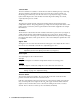
Pump Factory W ired Pressure Switch Factory W ired Green W hite Black Green W hite Red Oxygen Sensor IR CO2 Sensor Connector CO & H2S S ensors P lug Into Far Side of Pream p Circuit Board CO H2S Dumm y Plug IR CO2 Sensor Figure 6: Internal (Factory) Wiring, Sample-Draw Detector 35-3010RK-06-02 Sample-Draw Detector • 11
Start Up This section describes procedures to start up the sample-draw detector and place the sample-draw detector into normal operation. Introducing Incoming Power 1. Complete the installation procedures described earlier in this manual. 2. Verify that the power wiring to the controller is correct and secure. Seee the controller operator’s manual. 3. Turn on or plug in the incoming power at the controller, then turn on the controller. 4. Verify that the controller is on and operating properly. 5.
If the display reading is a typical background CO2 level, the detector is in normal operation. If the display reading is not a typical background CO2 level, perform a zeroing operation at the controller. See the controller operator’s manual for instructions. 6. Verify a reading of 20.9% oxygen on the oxygen channel at the controller. If the display reading is 20.9% oxygen, the oxygen detector is in normal operation. If the display reading is not 20.
at the amp 1 test point), and background concentration for the CO2 channel. Typical background concentrations of CO2 vary from 200 to 400 ppm depending on location. Investigate significant changes in the reading. Monthly This procedure describes a test to verify that the sample-draw detector responds properly to the target gases. Preparing for the response test CAUTION: This procedure may cause alarms at the monitoring device.
Fail Condition Symptoms • The sample-draw detector’s Fail light is on. • The controller is operating properly but indicates a reading well below zero on one or more channels. Probable causes • The sample-draw detector’s flow rate is too low because of an obstructed sample line, failed pump, etc. • The sample-draw detector is malfunctioning. • The sensor or detector wiring is disconnected or misconnected. Recommended action 1.
4. If the calibration/response difficulties continue, replace the sensor as described later in this section. 5. If the calibration/response difficulties continue, contact RKI Instruments, Inc. for further instruction. Replacing Components of the Sample-Draw Detector This section includes procedures to replace the oxygen sensor, the carbon monoxide sensor, the carbon dioxide sensor, the hydrophobic filter, and the charcoal filter. Replacing the Oxygen Sensor 1. Turn off or unplug incoming power. 2.
5. Plug the new detector into the circuit board. 6. Reinstall the circuit board to the flow block. 7. Turn on or plug in power. 8. Calibrate the replacement sensor as described in “Calibration, CO2 Detector” on page 20. Replacing the Hydrophobic Filter 1. Turn off or unplug power to the controller. 2. Locate the hydrophobic filter. It is just to the left of the main circuit board. 3. Grasp the hydrophobic filter and pull it out of its metal clamp. 4.
Calibration Frequency Although there is no particular calibration frequency that is correct for all applications, a calibration frequency of every 3 months is adequate for most oxygen and CO detector applications and every 6 months for most infrared CO2 applications. Unless experience in a particular application dictates otherwise, RKI Instruments, Inc. recommends a calibration frequency of every 3 months for the oxygen and CO detectors and every 6 months for the infrared CO2 detector.
Setting the Zero Reading NOTE: If you can verify a fresh air environment, it is not necessary to use the CO2 in nitrogen calibration cylinder to set the zero reading. 1. Screw the regulator into the CO2 in nitrogen calibration cylinder. 2. Connect the calibration kit sample tubing to the regulator. 3. Connect the sample tubing from the regulator to the inlet line at or near the INLET fitting. 4. Allow the gas to flow for one minute. 5.
Calibration, CO2 Detector This section describes how to calibrate the CO2 sensor in the sample-draw detector. It includes procedures to set the zero reading, set the response reading, and return to normal operation. NOTE: This procedure describes calibration using a demand flow regulator, a CO2 calibration cylinder, and a 3-gas calibration cylinder. Setting the Zero Reading CAUTION: This procedure may cause alarms at the monitoring device.
NOTE: For convenience, leave the regulator attached to the sample tubing. Returning to Normal Operation 1. Reconnect the incoming sample line. 2. Wait 1 to 2 minutes to allow the calibration gas to be drawn out and the reading to stabilize. 3. Close the housing door. 4. Store the components of the calibration kit in a safe and convenient place. Calibration, Oxygen Detector This section describes how to calibrate the oxygen detector in the sample-draw detector.
3. Follow the directions in the controller’s operator’s manual for setting the zero reading for the oxygen channel. 4. When the instructions call for applying gas to the detector, connect the sample tubing from the regulator to the inlet line at or near the INLET fitting. 5. Allow the gas to flow for one minute. 6. Set the zero reading according to the controller operator’s manual. 7. Disconnect the sample tubing from the inlet line. 8. Unscrew the regulator from the 3-gas calibration cylinder.