35-3010RK-05 Sample Draw Detector Part Number: 71-0210RK Revision: B Released: 9/10/12 www.rkiinstruments.
WARNING Read and understand this instruction manual before operating detector. Improper use of the detector could result in bodily harm or death. Periodic calibration and maintenance of the detector is essential for proper operation and correct readings. Please calibrate and maintain this detector regularly! Frequency of calibration depends upon the type of use you have and the sensor types.
Product Warranty RKI Instruments, Inc. warrants gas alarm equipment sold by us to be free from defects in materials, workmanship, and performance for a period of one year from date of shipment from RKI Instruments, Inc. Any parts found defective within that period will be repaired or replaced, at our option, free of charge.
Table of Contents Overview . . . . . . . . . . . . . . . . . . . . . . . . . . . . . . . . . . . . . . . . . . . . . . . . . . . . . . . . . . . . . . . . . . . 1 Specifications. . . . . . . . . . . . . . . . . . . . . . . . . . . . . . . . . . . . . . . . . . . . . . . . . . . . . . . . . . . . . . . . 1 Description . . . . . . . . . . . . . . . . . . . . . . . . . . . . . . . . . . . . . . . . . . . . . . . . . . . . . . . . . . . . . . . . . . 2 Housing . . . . . . . . . . . . . . . . . . . . . . . . . .
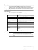
Overview This manual describes the 35-3010RK-05 sample draw detector. This manual also describes how to install, start up, maintain, and calibrate the detector head when it is used with a gas monitoring controller. A parts list at the end of this manual lists replacement parts and accessories for the detector head. Specifications Table 1 lists specifications for the 35-3010RK-05.
Description This section describes the components of the 35-3010RK-05 sample draw detector head. The sample draw detector consists of the housing, flow system, and detection system.
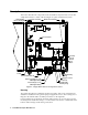
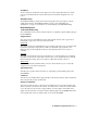
An aluminum subpanel is mounted to the interior of the housing. The sample draw detector’s internal components are mounted to the subpanel. Flow System The sample draw detector’s flow system consists of the INLET fitting, hydrophobic filter, charcoal filter, pump, flowmeter, bypass valve, status lights, pressure switch, flow block, and EXHAUST fitting (see Figure 1). Figure 2 illustrates how the gas sample moves through the flow system.
Charcoal Filter The charcoal filter is located in the top left corner of the enclosure. It is held in place by a metal clip. The charcoal filter is placed after the H2S sensor and before the CO sensor in the flow system. It scrubs out interfering gasses which may cause the CO sensor to respond, such as H2S or certain hydrocarbons. Replace the charcoal filter when false high CO readings are noticed, especially in the presence of H2S.
Flow Block The flow block is located in the lower right corner of the sample draw detector. All the sensors are installed in the flow block. The flow block routes the sampled air to each sensor. EXHAUST Fitting The EXHAUST fitting on the bottom of the housing allows the gas sample to exit the sample draw detector. The EXHAUST fitting accepts 1/4 in. rigid tubing. See “Installation” on page 8 for instructions to connect tubing to the EXHAUST fitting.
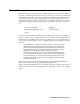
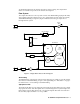
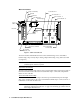
Main Circuit Board Pump Terminal Stip Test Point CAL - 1 Fail LED Test Point CAL + 1 Flowmeter Test Point CAL - 2 Flow Adjust Pot Test Point CAL + 2 Low Flow Adjust Reset Switch Pilot LED Relay Pressure Switch Zero Span Amp 1 (CO) Interconnect Terminal Strip Zero Span Amp 2 (H2S) Sensor/Transmitter Terminal Strip AC Terminal Strip Not Used Figure 3: Main Circuit Board The main circuit board includes the interconnect terminal strip, sensor/transmitter terminal strip, amp 1 circuit, amp 2 cir
Amp 1 and Amp 2 Circuits These circuits are located to the left of the sensor/transmitter terminal strip. They each include test points, a zero pot, and a span pot. Amp 1 is on the left and is for the CO channel. Amp 2 is on the right and is for the H2S channel. The zero and span pots are used during calibration. Use the span pot to make adjustments to gas response readings and the zero pot to make adjustments to the zero reading.
Installation This section describes procedures to mount the sample draw gas detector in the monitoring environment and wire the sample draw detector to a controller. Mounting the Sample Draw Detector 1. Select the mounting site. Consider the following when you select the mounting site.
6. Position the sample draw housing on a vertical surface at eye level (4 1/2 to 5 feet from the floor). 7. Insert 1/4 in. or 5/16 in. screws through the slots in the mounting feet to secure the housing to the mounting surface. Connecting the Sample Lines to the Sample Draw Detector 1. Attach 1/4 in. O.D. rigid polypropylene or rigid Teflon sample tubing to the INLET fitting.
Sample Draw Housing Main Circuit Board Interconnect T erm inal Strip Controller Oxygen + (W ) Terminals (G) CO Controller Transmitter Terminals 24 VDC + S (4/20 mA) 24 VDC - Figure 5: External (Field) Wiring, Sample Draw Detector 10 • 35-3010RK-05 Sample-Draw Detector
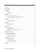
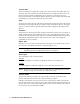
Pump Factory Wired Pressure Switch Factory W ired Green White Oxygen Sensor CO Sensor Plugs Into Far Side of Preamp Circuit Board CO H2S Figure 6: Internal (Factory) Wiring, Sample Draw Detector 35-3010RK-05 Sample-Draw Detector • 11
Start Up This section describes procedures to start up the sample draw detector and place the sample draw detector into normal operation. Introducing Incoming Power 1. Complete the installation procedures described earlier in this manual. 2. Verify that the power wiring to the controller is correct and secure. See the controller operator’s manual. 3. Turn on or plug in the incoming power at the controller, then turn on the controller. 4. Verify that the controller is on and operating properly. 5.
the controller. See the controller operator’s manual for directions. 6. Remove the voltmeter from the test points. 7. Close the housing door. Operation Normal Operation During normal operation, the Pilot LED will be on and the flowmeter will indicate about 1.2 SCFH. The current gas readings will be indicated at the controller. See the controller’s operator’s manual for a description of the reading indications. Low Flow Alarm If the flowrate falls below 0.6 SCFH (±0.
1. Verify that the controller is reading 20.9% for the oxygen channel and 0 ppm for the CO channel. If the reading is not as described above, set the zero (fresh air) reading as described in “Start Up” on page 12, then continue this procedure. 2. Assemble the calibration kit as described in the Calibration section of this manual. Use of a 3-gas cylinder is recommended so that both channels may be checked at once.
3. Verify that the sensor wiring is correct and secure. “Wiring the Sample Draw Detector” on page 9 describes detector wiring connections. 4. Calibrate the problem channel or channels as described in the Calibration section. 5. If the fail condition continues, replace the sensor from the problem channel or channels as described later in this section. 6. If the fail condition continues, contact RKI Instruments, Inc. for further instruction.
6. Place the sensor in the oxygen sensor cavity, then position the retaining plate on the two standoffs. 7. Secure the retaining plate to the standoffs with the two screws you removed in step 3. 8. Turn on incoming power. 9. Calibrate the replacement sensor as described in “Calibration, Oxygen Detector” on page 17. Replacing the CO Sensor 1. Turn off incoming power. 2. Open the housing door of the sample draw detector. 3. Unscrew the 5 screws that retain the preamp circuit board. 4.
If the sample draw detector goes into low flow alarm before you can adjust the flow down to 0.6 SCFH, adjust the low flow potentiometer 1/4 turn clockwise, then attempt to set the flow again. Repeat this step until you are able to adjust the flow to 0.6 SCFH. 2. Slowly turn the low flow potentiometer counterclockwise just until the sample draw detector goes into low flow alarm. NOTE: The low flow potentiometer is accessible through a circular cutout in the main circuit board. The cutout is labeled PS1. 3.
2. Connect the calibration kit sample tubing to the regulator. 3. Follow the directions in the controller’s operator’s manual for setting the zero reading for the oxygen channel. 4. When the instructions call for applying gas to the detector, connect the sample tubing from the regulator to the inlet line at or near the INLET fitting. 5. Allow the gas to flow for one minute. 6. Set the zero reading according to the controller operator’s manual. 7. Disconnect the sample tubing from the inlet line.
Preparing for Calibration CAUTION: This procedure may cause alarms at the controller. Take appropriate action to avoid this, such as entering the calibration mode at the controller. 1. Place the controller into its calibration program or disable external alarms. 2. Open the housing door. 3. Set a voltmeter to measure in the millivolt (mV) range. It will be used in the calibration of the CO channel. 4.
NOTE: For convenience, leave the regulator connected to the sample tubing. Returning to Normal Operation 1. Remove the voltmeter leads from the test points. 2. Reconnect the incoming sample line. 3. Wait 1 to 2 minutes to allow the calibration gas to be drawn out and the reading to stabilize. 4. Close the housing door. 5. Store the components of the calibration kit in a safe and convenient place. Parts List Table 2 lists replacement parts and accessories for the sample draw gas detector.