
Instruction Manual
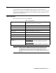

35-3010RK-04 Sample-Draw Detector • 3
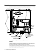
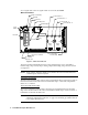
An aluminum subpanel is mounted to the interior of the housing. The sample draw
detector’s internal components are mounted to the subpanel.
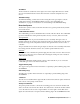
Flow System
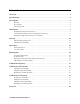
The sample draw detector’s flow system consists of the INLET fitting, hydrophobic filter,
charcoal filter, pump, flowmeter, bypass valve, status lights, pressure switch, flow block,
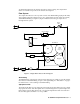
and EXHAUST fitting (see Figure 1). Figure 2 illustrates how the gas sample moves
through the flow system.
Figure 2: Sample Draw Detector Flow Diagram
INLET Fitting
The INLET fitting on the bottom of the housing allows the gas sample to enter the sample
draw detector. The INLET fitting accepts 1/4 in. rigid tubing. See “Installation” on page 8
for instructions to connect tubing to the INLET fitting.
Hydrophobic Filter
The hydrophobic filter is to the left of the main circuit board. It is held in place by a metal
clip. It prevents water and other liquids from contaminating the flow system. Replace the
filter when it appears dirty, discolored, or clogged. If a liquid other than water is drawn
into the filter, replace the filter as soon as possible.
Oxygen
Exhaust
CO
Cha r coal Fi l t er
LEL
Dummy
Plug
H2S
Dummy
Plug Us ed
Bypass
Va l v e
Flow Block
Pres sure Swit ch
Hydrophobic
Fi l ter
Pump
Inlet
Fl ow mete r