35-3010RK-02 Sample-Draw Detector Part Number: 71-0208RK Revision: C Released: 9/24/13 www.rkiinstruments.
WARNING Read and understand this instruction manual before operating detector. Improper use of the detector could result in bodily harm or death. Periodic calibration and maintenance of the detector is essential for proper operation and correct readings. Please calibrate and maintain this detector regularly! Frequency of calibration depends upon the type of use you have and the sensor types.
Product Warranty RKI Instruments, Inc. warrants gas alarm equipment sold by us to be free from defects in materials, workmanship, and performance for a period of one year from date of shipment from RKI Instruments, Inc. Any parts found defective within that period will be repaired or replaced, at our option, free of charge.
Table of Contents Overview . . . . . . . . . . . . . . . . . . . . . . . . . . . . . . . . . . . . . . . . . . . . . . . . . . . . . . . . . . . . . . . . . . . 1 Specifications. . . . . . . . . . . . . . . . . . . . . . . . . . . . . . . . . . . . . . . . . . . . . . . . . . . . . . . . . . . . . . . . 1 Description . . . . . . . . . . . . . . . . . . . . . . . . . . . . . . . . . . . . . . . . . . . . . . . . . . . . . . . . . . . . . . . . . . 2 Housing . . . . . . . . . . . . . . . . . . . . . . . . . .
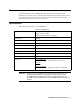
Overview This manual describes the 35-3010RK-02 sample draw detector. This manual also describes how to install, start up, maintain, and calibrate the sample draw detector when it is used with a gas monitoring controller. A parts list at the end of this manual lists replacement parts and accessories for the detector. Specifications Table 1 lists specifications for the 35-3010RK-02.
Description This section describes the components of the 35-3010RK-02 sample draw detector. The sample draw detector consists of the housing, flow system, and detection system.
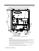
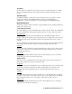
Flow System The sample draw detector’s flow system consists of the INLET fitting, hydrophobic filter, charcoal filter, pump, flowmeter, bypass valve, status lights, pressure switch, flow block, and EXHAUST fitting (see Figure 1). Figure 2 illustrates how the gas sample moves through the flow system.
Charcoal Filter The charcoal filter is located in the top left corner of the enclosure. It is held in place by a metal clip. The charcoal filter is placed after the H2S sensor and before the CO sensor (if one is installed) in the flow system. It scrubs out interfering gases which may cause the CO sensor to respond, such as H2S or certain hydrocarbons. It is included in this version of the sample draw detector in case a CO sensor is added in the field.
Flow Block The flow block is located in the lower right corner of the sample draw detector. All the sensors are installed in the flow block. The flow block routes the sampled air to each sensor. EXHAUST Fitting The EXHAUST fitting on the bottom of the housing allows the gas sample to exit the sample draw detector. The EXHAUST fitting accepts 1/4 in. rigid tubing. See “Installation” on page 8 for instructions to connect tubing to the EXHAUST fitting.
CO Dummy Plug The CO sensor position in the flow block is occupied by a plastic dummy plug in the 35-3010RK-02. Hydrogen Sulfide Gas Sensor The hydrogen sulfide gas sensor is installed in the upper right side of the flow block. It has 4 pins which mate with sockets on the preamp circuit board. Preamp Circuit Board The preamp circuit is used to connect the CO and H2S sensors to the main circuit board and to secure the sensors in the flow block.
Interconnect Terminal Strip The interconnect terminal strip is the sixteen-point terminal strip near the bottom edge of the main circuit board. Use the interconnect terminal strip to connect the sample draw detector to the controller. Sensor/Transmitter Terminal Strip The sensor/transmitter terminal strip is the sixteen-point terminal strip near the right edge of the circuit board. Use the sensor/transmitter terminal strip to connect sensors or transmitters to the main circuit board.
Installation This section describes procedures to mount the sample draw gas detector in the monitoring environment and wire the sample draw detector to a controller. Mounting the Sample Draw Detector 1. Select the mounting site. Consider the following when you select the mounting site.
6. Position the sample draw housing on a vertical surface at eye level (4 1/2 to 5 feet from the floor). 7. Insert 1/4 in. or 5/16 in. screws through the slots in the mounting feet to secure the housing to the mounting surface. Connecting the Sample Lines to the Sample Draw Detector 1. Attach 1/4 in. O.D. rigid polypropylene or rigid Teflon sample tubing to the INLET fitting.
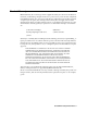
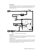
Sample Draw Housing Main Circuit Board Interconnect Term inal Strip Controller L EL Terminals R W G B Controller O xygen + (W ) Terminals (G) CO (Controller Transmitter Terminals) 24 VDC + S (4/20 mA) 24 V DC S (4/20 mA ) 24 V DC + H2S (Controller Transmitter Terminals) Figure 5: External (Field) Wiring, Sample Draw Detector 10 • 35-3010RK-02 Sample-Draw Detector
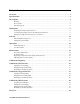
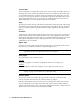
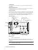
Pump Factory Wired Pressure Switch Factory Wired Green White Black Green White Red Oxygen Sensor LEL Sensor Connector CO & H2S Sensors Plug Into Far Side of Preamp Circuit Board CO H2S LEL Detector Figure 6: Internal (Factory) Wiring, Sample Draw Detector 35-3010RK-02 Sample-Draw Detector • 11
Start Up This section describes procedures to start up the sample draw detector and place the sample draw detector into normal operation. Introducing Incoming Power 1. Complete the installation procedures described earlier in this manual. 2. Verify that the power wiring to the controller is correct and secure. See the controller instruction manual. 3. Turn on or plug in the incoming power at the controller, then turn on the controller. 4. Verify that the controller is on and operating properly. 5.
the controller instruction manual for directions. 6. Verify a reading of 20.9% oxygen at the controller. If the display reading is 20.9% oxygen, the oxygen detector is in normal operation. If the display reading is not 20.9% oxygen, perform a fresh air adjustment operation at the controller. See the controller instruction manual for directions. 7. Remove the voltmeter from the test points. 8. Close the housing door.
Monthly This procedure describes a test to verify that the sample draw detector responds properly to the target gases. Preparing for the response test CAUTION: This procedure may cause alarms at the monitoring device. Take appropriate action to avoid this, such as entering the calibration mode at the monitoring device. 1. Verify that the controller is reading 0 for the combustible and H2S channels and 20.9 for the oxygen channel. If the reading is not 0 on the combustible or H2S channels or 20.
Probable Causes • The sample draw detector’s flow rate is too low because of an obstructed sample line, failed pump, etc. • The sample draw detector is malfunctioning. • The sensor or transmitter wiring is disconnected or misconnected. Recommended Action 1. At the sample draw detector, set the correct flow rate with the bypass valve or flow adjust potentiometer. 2. If you cannot set the correct flow rate, check the sample lines for obstructions or kinks. 3.
Replacing Components of the Sample Draw Detector This section includes procedures to replace the sensors, the hydrophobic filter, and the charcoal filter. Replacing the Combustible Sensor 1. Turn off incoming power. 2. Open the housing door of the sample draw detector. 3. Unscrew and remove the two screws that secure the retaining plate, then lift the plate, connector, and sensor out of the housing. 4. Unplug the connector from the sensor. 5.
7. Reinstall the preamp circuit board with the sensors onto the flow block. 8. Turn on incoming power. 9. Calibrate the replacement sensor as described in “Calibration, H2S Detector” on page 20. Replacing the Hydrophobic Filter 1. Turn off or unplug power to the controller. 2. Locate the hydrophobic filter. It is just to the left of the main circuit board. 3. Grasp the hydrophobic filter and pull it out of its metal clamp. 4.
Calibration Frequency Although there is no particular calibration frequency that is correct for all applications, a calibration frequency of every 3 months is adequate for most sample draw detector applications. Unless experience in a particular application dictates otherwise, RKI Instruments, Inc. recommends a calibration frequency of every 3 months for the sample draw detector.
reading for the LEL channel. 4. When the instructions call for applying gas to the detector, connect the sample tubing from the regulator to the inlet line at or near the INLET fitting. 5. Allow the calibration gas to flow for 1 minute. 6. Set the response reading according to the controller operator’s manual to match the calibration gas concentration. 7. Disconnect the sample tubing from the inlet line. 8. Unscrew the regulator from the calibration cylinder.
7. Disconnect the sample tubing from the inlet line. 8. Unscrew the regulator from the 4-gas calibration cylinder. 9. For convenience, leave the regulator attached to the sample tubing. Setting the Fresh Air Reading CAUTION: This procedure may cause alarms at the controller. Take appropriate action to avoid this, such as entering the calibration mode at the controller.
board. Plug the positive lead into the test point labeled CAL+2; plug the negative lead into the test point labeled CAL-2. 4. Use the following formula to determine the correct test points output for the H2S calibrating sample. Output (mV) = (calibrating sample/fullscale) X 400 + 100 For example, with a calibrating sample of 25 ppm H2S and a fullscale setting of 100 ppm H2S, the correct output for the H2S test points is 200 mV. 200 (mV) = (25/100) X 400 +100 Setting the Zero Reading 1.
5. Store the components of the calibration kit in a safe and convenient place. Parts List Table 4 lists replacement parts and accessories for the sample draw gas detector.