
Manual

35-3001A-05-02 Carbon Dioxide Sample-Draw Detector • 11
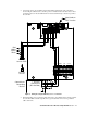
8. Connect the wires to the applicable detector/transmitter terminal strip at the controller as
shown in Figure 5. Refer to the controller operator’s manual and the controller detector head
specification sheet for the 35-3001A-05-02 for detector/terminal strip connections specific to
the controller.
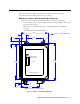
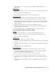
Figure 5: Wiring the Sample-Draw Detector to a Controller
9. If shielded cable is used, connect the cable’s drain wire to an available chassis (earth) ground at
the controller. RKI controllers typically have a ground stud that can be used to ground the
cable’s drain wire.
Not Used on
This Version
ZE RO
S
PWR / SIG
SP AN
OXY LEL/IR
Green
Black
Red
White
PATS201PATS201
AMP 1
AMP 1
OXY
LEL/ IR
+24VDC
Controller or
Recording
Device
AMP 2
4/20 Signal
-(DCGround)
IR CO2
Sensor PCB
AMP 2
PATS101PATS101
Sensor
Current
148m A
IR CO2
Sensor
W
LEL
GBR