
Manual

10 • 35-3001-06-01 Combustible Gas/Oxygen Sample-Draw Detector
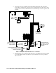
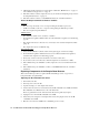
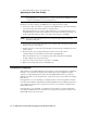
8. Connect the wires to the applicable detector/transmitter terminal strip at the controller as
shown in Figure 5. Refer to the controller operator’s manual and the controller detector head
specification sheet for the 35-3001-06-01 for detector/terminal strip connections specific to the
controller.
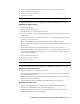
Figure 5: Wiring the Sample-Draw Detector to a Controller
9. If shielded cable is used, connect the cable’s drain wire to an available chassis (earth) ground at
the controller. RKI controllers typically have a ground stud that can be used to ground the
cable’s drain wire.
White
Green
Black
Red
LE L/IR
PATS101PATS101PATS201PATS201
LE L/IROXY
Controller Detector/
Transmitter Termina
l
Strip, LEL Detector
Terminals
OXY
Black
Green
White
Red
AMP 1
Black (-)
White (+)
AMP 1 AMP 2
Controller Detector/
Transmitter Terminal
Strip Terminals
White
Green
Controller Detector/Transmitter
Terminal Strip, Oxygen
DetectorTerminals
- (DC Ground)
+ 24 VDC
Oxygen
Sensor
IR Combustible
Sensor PCB
AMP 2