
Manual

2 • Sample-Draw Hydrogen Sulfide Gas Detection
Description
This section describes the components of the sample-draw hydrogen sulfide gas detector.
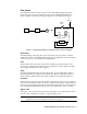
The sample-draw detector consists of the housing, flow system, and detection system.
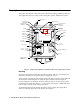
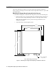
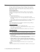
Figure 1: Sample-draw Hydrogen Sulfide Gas Detector Component Location
Housing
The sample-draw detector’s fiberglass housing is weather- and corrosion-resistant. It is
suitable for installation where general purpose equipment is in use.
The housing door is hinged on the left side and is secured by two latches on the right side.
The flowmeter and status lights are visible through a window in the housing door.
Four mounting feet are attached to the back of the housing (one at each corner). Use the
mounting feet to install the housing to a vertical surface. Use the two conduit hubs on the
bottom of the housing to make wiring connections.
An aluminum subpanel is mounted to the interior of the housing. The sample-draw
detector’s internal components are mounted to the subpanel.
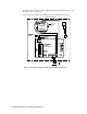
Transmitter
Terminal Strip
Interconnect Terminal
Strip
Main Circuit Board
SPAN
G
OXY
24V
FB
4/20BATT
BKRD W
TOXIC
ZERO
TOX IC
OXY
Pilot LED
Bypass va lve
Flowmeter
3/4" Conduit
Hub, 2X
JUM PER PINS FOR
FACTORY USE
ONLY
Particle filter
Transmitter
Pump/flow switch
terminal block
Flow Alarm Setpoint
Adjustment
Potentiometer
Mounting Foot,
4X
Flow Adjust
Potentiometer
Fail LED
Exhaust
Inlet
Sensor
Connector
Span Pot
Zero Pot
Test Points
100 - 500 mV range
Not U sed
Hydrogen Sulfide Sensor
Factory Set Pot