Sample-Draw Hydrogen Sulfide Gas Detector for Use With Generic Device Specifications Table 1 lists specifications for the sample-draw hydrogen sulfide detector. . Table 1: Specifications Target Gas Hydrogen Sulfide Input Power 24 VDC Output Signal 4-20 mA Construction (housing) Fiberglass/polyester (NEMA 4X) Dimensions 8.5 in. H x 6.5 in. W x 4.25 in. D Weight 4.5 lbs. Sampling Method Sample-draw Sample Flow 1.
Description This section describes the components of the sample-draw hydrogen sulfide gas detector. The sample-draw detector consists of the housing, flow system, and detection system.
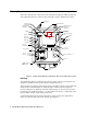
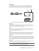
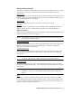
Flow System The sample-draw detector’s flow system consists of the INLET fitting, filter, pump, flowmeter, bypass valve, status lights, pressure switch, and EXHAUST fitting (see Figure 1). Figure 2 illustrates how the gas sample moves through the flow system.
Status lights Two status lights are above the flowmeter. They are also visible through the window in the housing door. Pilot light The green Pilot light is on when the sample-draw detector is receiving power from the Pioneer. Fail light The red Fail light is on when the sample flow rate is below the low flow level. NOTE: The default low flow level is 0.6 SCFH (±0.2). See “Adjusting the Low Flow Setting” on page 13 to adjust this setting.
Hydrogen Sulfide Transmitter The hydrogen sulfide transmitter is mounted to the left of the hydrogen sensor. It consists of the span pot, zero pot, two internally wired terminal strips, and the test points. Span/zero pots The span and zero pots are located at the left edge of the transmitter and are used for calibration.
Installation This section describes procedures to mount the sample-draw hydrogen sulfide gas detector in the monitoring environment and wire the sample-draw detector to power and an external device. Mounting the Sample-Draw Combustible Gas Detector 1. Select the mounting site. Consider the following when you select the mounting site.
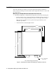
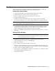
2. Close and latch the housing door. NOTE: The sample-draw detector is shipped with the mounting feet “tucked under” the housing to protect the mounting feet during shipment. 3. Slightly loosen the screw that secures the mounting foot to the housing, then rotate the mounting foot 180 degrees (see Figure 3). 4. Tighten the screw that secures the mounting foot to the housing. 5. Repeat steps 3 and 4 for the remaining three mounting feet. 6.
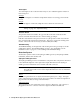
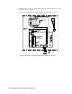
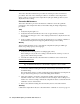
5. Route the cable or wires in conduit leading from the sample-draw detector to the monitoring device and power. 6. Connect the cable shield to an available chassis ground at the device end. H2S S ample Draw Housing Not Used H2S Sensor, Internally Connected FB BATT Transmitter, Internally wired 4/2 0 24V ZERO SPAN OXY TOXIC TOXIC RD B K OXY W G PUMP ASSY INTERNALLY WIRE D. P RESSURE S WITCH INTERNALLY WIRED.
Start Up This section describes procedures to start up the sample-draw hydrogen sulfide gas detector and place the sample-draw detector into normal operation. Introducing Incoming Power 1. Complete the installation procedures described earlier in this manual. 2. Verify that the power /device wiring is correct and secure. 3. Turn on or plug in the incoming power at the power source end. 4. Verify that the Pilot light is on. 5. Verify that the flowmeter indicates a flow rate of approximately 1.
Maintenance This section describes maintenance procedures. It includes preventive maintenance procedures. This section also includes procedures to troubleshoot the sample-draw detector, replace components of the sample-draw hydrogen sulfide gas detector, and adjust the low flow setting. Preventive Maintenance This section describes a preventive maintenance schedule to ensure the optimum performance of the sample-draw detector. It includes daily, monthly, and quarterly procedures. Daily 1.
Troubleshooting The troubleshooting guide describes symptoms, probable causes, and recommended action for problems you may encounter with the sample-draw hydrogen sulfide gas detector. NOTE: This troubleshooting guide describes sample-draw detector problems only. See the instruction manual for the monitoring device if it exhibits any problems. Fail condition Symptoms • The sample-draw detector’s Fail light is on. • The monitoring device is operating properly but indicates a reading well below zero.
Recommended action 1. Verify that the calibration cylinder contains an adequate supply of a fresh test sample. 2. If necessary, set the correct flow rate with the bypass valve or flow adjust potentiometer. 3. If you cannot set the correct flow rate, check the sample line for obstructions or kinks. 4. If the calibration/response difficulties continue, replace the sensor as described later in this section. 5. If the calibration/response difficulties continue, contact RKI Instruments, Inc.
ferrule into the nut. Insert the ferrule so the flat side is facing down. NOTE: Make sure the bottom ferrule is laying flat in the nut. 4. Insert the cone-shaped front ferrule on top of the bottom ferrule. Insert the ferrule so the smaller end of the cone is facing up. 5. Screw the nut onto the fitting, then connect the sample tubing to the fitting. Make sure you firmly tighten the tubing to the fitting. Adjusting the Low Flow Setting The factory-set low flow setting is 0.6 SCFH (±0.2).
Calibration This section describes how to calibrate the sample-draw combustible gas detector. It includes procedures to assemble the calibration kit, set the zero reading, set the response reading, and return to normal operation. NOTE: This procedure describes calibration using a gas collection bag. A demand-flow calibration kit is also available for calibrating the hydrogen sulfide gas sampledraw detector. Preparing for Calibration 1. Open the housing door. 2.
Setting the Zero Reading 1. Open the clamp, then connect the sample tubing from the gas collection bag to the sample-draw detector’s inlet line. This step is not necessary if you verified a fresh air environment earlier in this procedure. 2. Allow the reading to stabilize for approximately 1 minute. 3. Verify a voltmeter reading of 100 mV (± 2 mV). 4. If necessary, use a small flat-blade screwdriver to adjust the zero potentiometer until the voltmeter reading is 100 mV (± 2 mV). 5.
Parts List Table 4 lists replacement parts and accessories for the sample-draw hydrogen sulfide gas detector.