
User Manual


35-3000RK-LEL Combustilbe Gas Sample-Draw Detector • 7
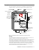
Status lights
Two status lights are above the flowmeter. They are also visible through the window in
the housing door.
Pilot light
The green Pilot light is on when the sample-draw detector is receiving power from the
controller.
Fail light
The red Fail light is on when the sample flow rate is below the low flow level.
NOTE:
The factory set low flow level is 0.6 SCFH (±0.2). See “Adjusting the Low Flow
Setting” on page 17 to adjust this setting.
Pressure switch
The pressure switch is mounted to the opposite side of the main circuit board. The
pressure switch monitors the flow rate of the incoming gas sample.
If the flow rate falls below the preset low flow level, the pressure switch causes the fail
relay to interrupt the signal from the detector. The interrupted detector signal causes a fail
condition at the controller. The low flow level is factory-set at 0.6 SCFH (±0.2 SCFH).
EXHAUST fitting
The EXHAUST fitting on the right side of the housing allows the gas sample to exit the
sample-draw detector. The EXHAUST fitting accepts 1/4 in. rigid tubing. See the
Installation section on page 9 to connect tubing to the EXHAUST fitting.
Detection System
The detection system consists of the combustible gas sensor and the main circuit board.
Combustible Gas sensor
The combustible gas sensor is installed in a cavity block. The cavity block is mounted to
the aluminum
subpanel near the bottom of the sample-draw detector. The combustible
gas sensor includes the sensing elements, flame arrestor, connector, and sensor leads.
NOTE:
The cavity block includes a cavity for an oxygen sensor. This version of the
sample-draw detector does not include the oxygen sensor.
Sensing elements
Two sensing elements are protected within the sensor assembly. Through a series of
thermal and electronic reactions, these elements produce an electrical output that is
proportional to the detection range of the sample-draw detector.
Flame arrestor
The porous flame arrestor allows the gas sample to enter the sensor assembly and contact
the sensing elements. The flame arrestor also contains any sparks that may occur within
the sensor.
Connector
The top of the sensor includes five pins that plug into the socket connector. This connector
allows you to replace the sensor without disconnecting the wiring. The sensor leads are
soldered to the connector.