
User Manual


6 • 35-3000RK-LEL Combustible Gas Sample-Draw Detector
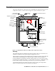
Flow System
The sample-draw detector’s flow system consists of the INLET fitting, hydrophobic filter,
pump, flowmeter, bypass valve, status lights, pressure switch, and EXHAUST fitting (see
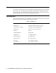
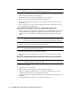
Figure 1). Figure 2 illustrates how the gas sample moves through the flow system.
Figure 2: Combustible Gas Sample-draw Detector Flow Diagram
INLET fitting
The INLET fitting on the right side of the housing allows the gas sample to enter the
sample-draw detector. The INLET fitting accepts 1/4 in. rigid tubing. See the Installation
section on page 9 to connect tubing to the INLET fitting.
Hydrophobic Filter
The hydrophobic filter is below the main circuit board. The filter prevents particulates and
water in the incoming gas sample from damaging the flow and detection systems. Replace
the filter when it appears dirty, discolored, or clogged.
Pump
The pump is behind the main circuit board near the top of the sample-draw detector.
The pump pulls the gas sample into the sample-draw detector. The pump operates on
24 VAC, which is generated from the 24 VDC supplied by the controller.
Flowmeter
The flowmeter is attached to the main circuit board near the top left corner (see Figure 1.)
You can see it through the window in the door. A ball in the flowmeter column indicates
the flow rate of the sample-draw detector. The flowmeter measures the flow in the range
0.2 to 2.0 SCFH (Standard Cubic Feet per Hour). The optimum flow rate is 1.5 SCFH.
Bypass valve
The bypass valve is to the left of the flowmeter. The bypass valve adjusts the flow rate to
the detector. Use a flat-blade screwdriver to adjust the bypass valve.
NOTE:
The bypass valve allows fine adjustments of the flow rate. For a wider range of
adjustment, use the flow adjust potentiometer (see Figure 1.)
Inlet Filter Pump Sensor
Flowmeter
Pressure Switch
Exhaust
To
Valve
Bypass