
Instruction Manual

35-3000RK-LEL/O Sample-Draw Detector • 9
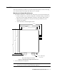
CAUTION: Do not route controller power wiring and detector wiring through the same hub.
The power cable may disrupt the transmission of the sensor signal to the controller.
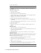
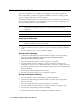
8. Connect the wires to the applicable detector terminal strip and power terminals at the
controller as shown in Figure 4. See the 35-3000RK-LEL/O detector head specification
sheet for your controller for the specific wiring connections to the controller.
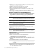
Figure 4: Wiring the Sample-Draw Detector to a Controller
5. If shielded cable is used, connect the cable’s drain wire to an available chassis (earth)
ground at the controller. RKI controllers typically have a ground stud that can be used
to ground the cable’s drain wire.
BLA CK
WHITE
GREEN
RD WHT
LEL/ O2
To oxygen
sensor
4/20GRN BLK GND 24V
+
AMP
RE D
RD
To LEL
Sensor
_
P- AMP
Green
White
BLKGRNWHT 4/20
P- A MPAMPLEL/ O2
_
+
24VGND
PSW
PU MP
PRESSURE
SWITCH
INTERN AL LY
WIRED.
PUMP ASSY
INTERN AL LY
WIRED.
CG N D
Controller LEL
Detector Terminals
Controller Terminals
Green
White
Red
Black
115VAC
NH
Green (-)
White (+)
Controller Oxygen
Detector Terminals
+24 VDC
- (DC Ground)
NOT USED
ON THIS
VERSION.
LEL/Oxygen Sample Draw Housing
PCB IN SINGLE POINT
SAMPLE DRAWING
DETECTOR ASSY.