
Manual

4 • 12 VDC Beacon 200 Operator’s Manual
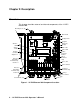
Chapter 2: Description
Overview
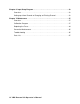
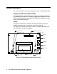
This chapter describes external and internal components of the 12 VDC
Beacon 200.
FACTORY
WIRED
NO NC CNO NC C
COM- A2COM- A1CH2-A2
NO NC C
CH1-A1
CH1-A2
Display PCB
Program
Button (4)
Fuses, DC
Power Switch
Button
Repeater
Buzzer
Fail LED
Pilot LED
Alarm Terminal
Strip
Relays
NO NC C
COM- FAIL
NO NC C
Detector/
Transmitter
Terminal Strip,
Channel 1
Display
Contrast
Adjust Pot
Alarm
1LED
Main PCB
DC In
Terminal
Strip
Reset
Switch
Mounting Foot, 4X
Buzzer
Conduit Hub (3X)
Controller
Terminal Stri
p
Detector/
Transmitter
Terminal Strip,
Channel 2
NO NC C
CH2- A1
NO NC C
Display
Alarm 2
LED
Figure 1. 12 VDC Beacon 200 Component Location