
Manual

12 VDC Beacon 200 Operator’s Manual • 13
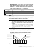
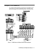
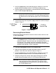
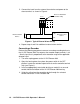
Wiring the 12 VDC Beacon 200
This section describes procedures to connect the 12 VDC power source,
external alarm(s), a recorder, and detector head(s). See Figure 5 for a
general wiring diagram of all external wiring to the 12 VDC Beacon 200.
COM-A1 COM-FAILCOM-A2
NO NC C NO NC CNO NC C
NOT
+
+
+
Chan ne l 1 Record er
1K M ax I mp eda nce
CH 2-A1CH 1-A2
NO NC C NO NC C
BUZ
Reset Switch
(Factory Wired)
Buzzer
(Factory Wired)
Oxygen
Detector
+ S
OXYGENAMP/PREAMP
+
Green
White
+ S
AMP/PREAMP OXYGEN
+
CHANNEL 2
USED
DC
In Terminal Strip Wiring
12 V
DC
CH1
OUT
LE L Dete ctor
Black
LEL
R W G B
Typical Detector/Transmitter Terminal
Strip Wiring
Only one detector or transmitter can be
wired to Ch1 or Ch2 at a time. See detector
head wiring diagram for specific wiring.
Typical Alarm Relay Terminal Strip
Wiring
CH 2-A2
NO NC C
BUZ +
RESET
RESET
2-Wire 4-20 ma
Transmitter
+ 24 V
Red
White
Green
+ 24 V
FB (4-20 mA)
LEL
R W G B
Contact Rating of 10 Amps at 115/
220 V~ Resistive or
10A @ 30V Resistive for
Each Set of Alarm Relay
Contacts.
Alarm Devices
Chan ne l 2 Record er
1K M ax I mp eda nce
CHANNEL 1
CH2
OUT
FB (4-20 mA)
Controller Terminal Strip
Wiring
4- 2 0mA Ou t
4- 2 0mA Ou t
NO N C C
CH1-A1
ALARM
DEVIC E
POWER
- DC GROUND
3-Wire 4-20 ma
Transmitter
Figure 5. 12 VDC Beacon 200 General External Wiring Diagram