
Instruction manual
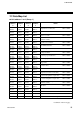
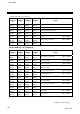
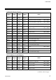
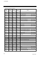
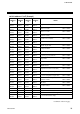
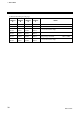
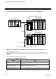
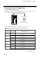
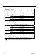
Table Of Contents
8. CURRENT TRANSFORMER (CT) MONITOR
IMS01J04-E2
33
8.1 Setting on The H-PCP-J Module Side
PLC data memory address setting
Set the data memory address of each control unit using the unit address setting switch at the front of
the H-PCP-J module. For this setting, use a small blade screwdriver.
8
7
6
5
4
3
2
1
0
F
E
D
C
B
A
9
H-PCP-J module
Setting range:
0 to 15 (0 to F: hexadecimal)
Unit address setting switch
Up to 16 SR Mini HG SYSTEMs can be connected to a PLC communication port.
Set unit address within address range of PLC (CPU unit) to use.
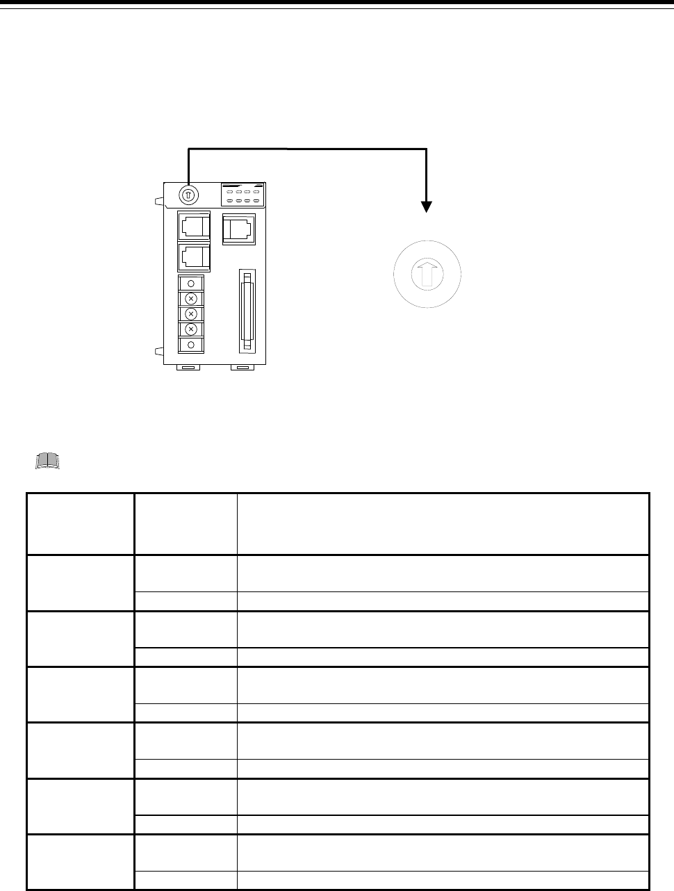
Unit address
setting
switch
PLC data
memory
address
Communication item
0
D9000 to
D9059
Unit address 0 Current transformer input measured value
CT1 to CT60
D9961 Unit address 0 PCP normal communication flag
1
D9060 to
D9119
Unit address 1 Current transformer input measured value
CT1 to CT60
D9962 Unit address 1 PCP normal communication flag
2
D9120 to
D9179
Unit address 2 Current transformer input measured value
CT1 to CT60
D9963 Unit address 2 PCP normal communication flag
3
D9180 to
D9239
Unit address 3 Current transformer input measured value
CT1 to CT60
D9964 Unit address 3 PCP normal communication flag
4
D9240 to
D9299
Unit address 4 Current transformer input measured value
CT1 to CT60
D9965 Unit address 4 PCP normal communication flag
5
D9300 to
D9359
Unit address 5 Current transformer input measured value
CT1 to CT60
D9966 Unit address 5 PCP normal communication flag
Continued on the next page.