
Instruction manual
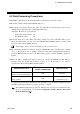
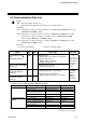
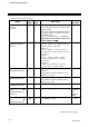
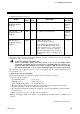
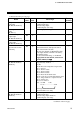
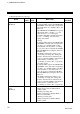
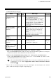
Table Of Contents

6. COMMUNICATION DATA
IMS01J04-E2
23
Continued from the previous page.
Name
Attri-
bute
Struc-
ture
Data range
Factory
set value
PCP normal
communication flag
[H-PCP-J]
RO
U
The numbers 0 and then 1 are repeated in
every communication period.
The SR Mini HG SYSTEM rewrites 0 and 1
in this area alternately like 0 1 0 in
every communication period. It is possible to
determine whether or not the SR Mini HG
SYSTEM makes communication by
monitoring this area periodically using the
PLC program.
Memory area number
[H-TIO-, H-CIO-A,
H-SIO-A]
WO U
1 to 8
Data reading is always made from the PLC
regardless of the request command. Any
numeric value other than 1 to 8 becomes
invalid.
Changing the memory area automatically
writes each set value to the PLC.
Control RUN/STOP
transfer *
[H-PCP-J]
WO U
0: Control STOP
1: Control RUN
PV bias
[H-TIO-, H-CIO-A,
H-SIO-A]
R/W C 5.00 to 5.00 % of span
ZK-1103 specification:
Input span to Input span
0.00
ZK-1103:
0
a
Setting change rate
limiter
[H-TIO-, H-CIO-A,
H-SIO-A]
R/W C 0.0 to 100.0 % of span/minute 0.0
*
When the control RUN/STOP holding setting is set to “Not hold” or “Hold”:
The control RUN/STOP transfer setting is always read from the PLC regardless of the request
command. Any numeric value other than 0 and 1 becomes invalid.
When the control RUN/STOP holding setting is set to “Start-up from control RUN status”:
As the control RUN/STOP transfer setting is always set to “1: Control RUN,” any value set to the
control RUN/STOP transfer becomes invalid.
The Control RUN/STOP holding (Identifier X1) is set by host communication. For the host
communication, see the Power Supply/CPU Module H-PCP-J Instruction Manual
(IMS01J02-E).
a
Unit (C, F, etc.) and decimal point position (No decimal place, One decimal place, Two decimal
places or Three decimal places) depends on input range type.