
Instruction manual
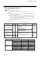
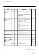
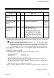
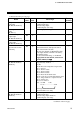
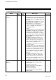
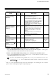
Table Of Contents

6. COMMUNICATION DATA
IMS01J04-E2
21
Continued from the previous page.
Name
Attri-
bute
Struc-
ture
Data range
Factory
set value
Temperature measured
value (PV)
[H-TIO-, H-CIO-A]
RO C
TC/RTD input:
Within input range
Current/voltage input:
Within display scale range
Motor speed measured
value
[H-SIO-A]
Within display scale range
Heat-side manipulated
output value
[H-TIO-, H-CIO-A]
RO C
0.5 to 105.0 %
Cool-side manipulated
output value
[H-TIO-, H-CIO-A]
RO C
0.5 to 105.0 %
Current transformer
input measured value
[H-CT-A]
RO C
0.0 to 100.0 A or 0.0 to 30.0 A
Current transformer (CT) input measured
value of the H-CT-A module.
Allocates the channels for H-TIO- module
to the input channels of H-CT-A module by
CT channel setting.
For the CT channel setting, see the Power
Supply/CPU Module H-PCP-J Instruction
Manual (IMS01J02-E).
TIO status
[H-TIO-, H-CIO-A,
H-SIO-A]
RO C
Each operation status is assigned as a bit
image in binary numbers.
Bit data
bit 0: Heat-side manipulated output status
bit 1: Unused
bit 2: Alarm 1 status
bit 3: Alarm 2 status
bit 4: Burnout status
bit 5: Heater break alarm status
bit 6: Control loop break alarm (LBA) status
bit 7: Temperature rise completion status
bit 8: Setting error
bit 9 to 15: Unused
Data 0: OFF 1: ON
bit 15 ·························· bit 0
Bit image: 0000000000000000
[Decimal number: 0 to 509]
Set value monitor
[H-TIO-, H-CIO-A,
H-SIO-A]
RO C
TC/RTD input:
Within input range
Current/voltage input, H-SIO-A:
Within display scale range
Continued on the next page.