
Instruction manual
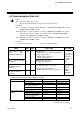
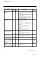
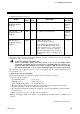
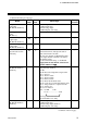
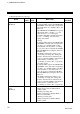
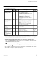
Table Of Contents

6. COMMUNICATION DATA
IMS01J04-E2
18
Continued from the previous page.
Name
Attri-
bute
Struc-
ture
Data range
Factory
set value
Heater break alarm
set value
[H-CT-A]
R/W C
0.0 to 100.0 A or 0.0 to 30.0 A
For the current transformer (CT) input of the
H-CT-A module.
Allocates the channels for H-TIO- module
to the input channels of H-CT-A module by
CT channel setting.
For the CT channel setting, see the Power
Supply/CPU Module H-PCP-J Instruction
Manual (IMS01J02-E).
0.0
Operation mode transfer
[H-TIO-, H-CIO-A,
H-SIO-A]
R/W C
0: Unused
If set to “Unused,” no control, monitor or
alarm monitor is performed.
1: Monitor
If set to “Monitor,” only the monitor is
performed. No control or alarm monitor is
performed.
2: Alarm
If set to “Alarm,” monitor or alarm
monitor is performed. No control is
performed.
3: Normal
Selected to normal mode to perform
control, monitor or alarm monitor.
3
Auto/Manual transfer
[H-TIO-, H-CIO-A]
R/W C
0: Auto
1: Manual
Setting will be invalid in ON/OFF control
and heat/cool control.
0
Manual output value
[H-TIO-, H-CIO-A]
R/W C
5.0 to 105.0 %
Setting will be invalid in ON/OFF control
and heat/cool control.
0.0
Overlap/deadband
[H-TIO-, H-CIO-A]
R/W C 10.0 to 10.0 % of span 0.0
Heat-side proportional
band
[H-TIO-, H-CIO-A,
H-SIO-A]
R/W C 0.1 to 1000.0 % of span
H-TIO-,
H-CIO-A:
3.0
H-SIO-A:
300.0
Cool-side proportional
band
[H-TIO-, H-CIO-A]
R/W C 0.1 to 1000.0 % of span 3.0
Continued on the next page.