
Instruction manual
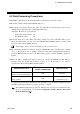
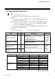
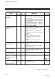
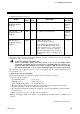
Table Of Contents
6. COMMUNICATION DATA
IMS01J04-E2
15
6.2 Data Processing Precautions
With PLC communication, the maximum number of channels per unit address is 20.
Read data of unused channel and undefined address is 0.
The data type is treated as binary data with a sign and without a decimal point. For this reason,
carefully express and set the data. (excluding the TIO status)
[Example] Heat-side proportional band
Initial value of internal data: 3.0
Communication data: 30
If the data range error occurs during data setting, “Setting error” (bit 8 in the TIO status) is set to
ON in the channel where the error occurs. The SR Mini HG SYSTEM continues operation at the
present set value without updating the data.
Any attempt to write to an unused channel is not processed as an error.
The autotuning (AT) function starts its execution with PID/AT transfer and the request command
set to “1: AT operation” and “1: Setting,” respectively. After the autotuning function finishes its
execution, PID/AT transfer returns to “0: PID control operation” and thus the PID constants are
updated.
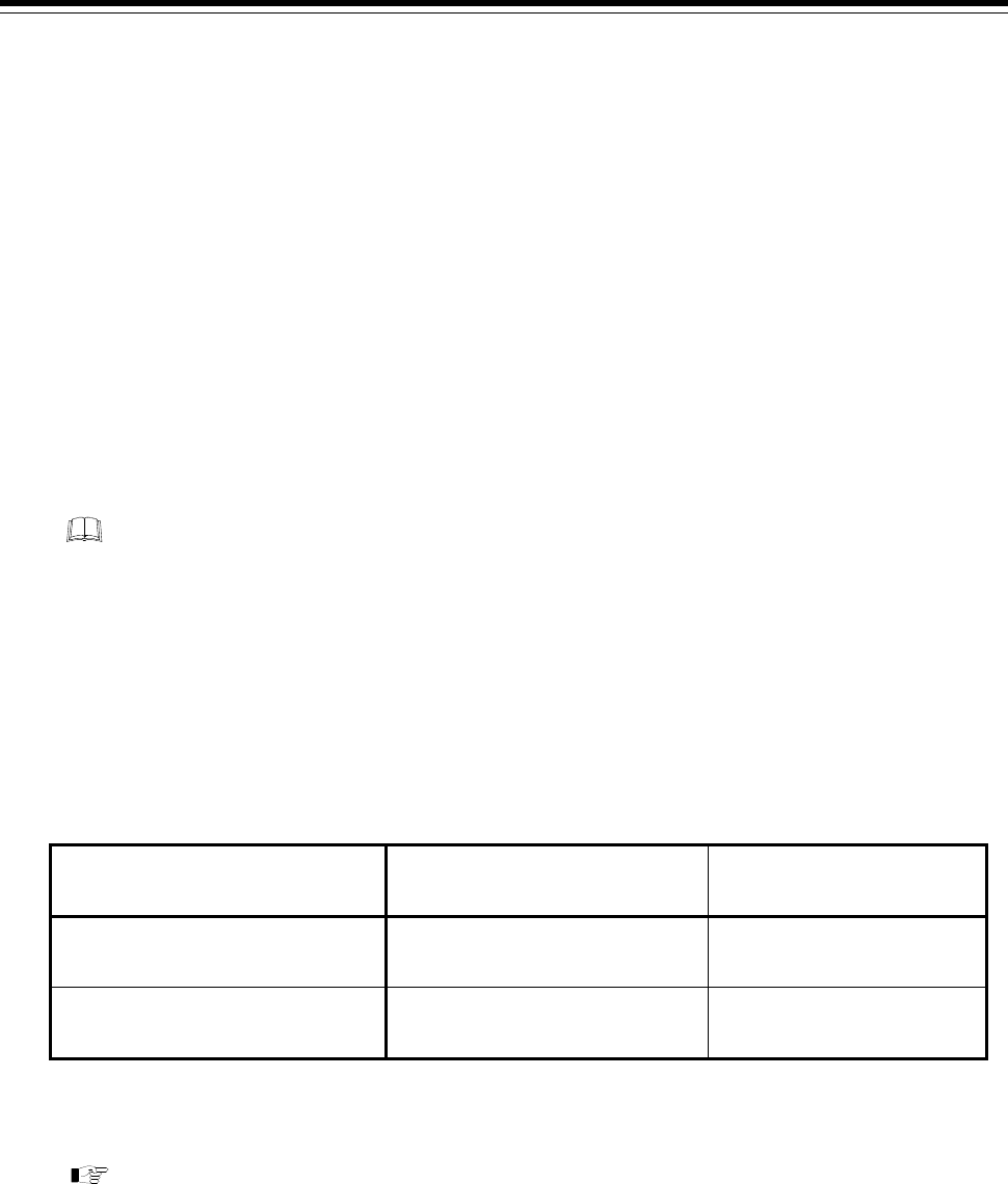
When the PLC communication status is selected by selecting the H-PCP-J module DO type
(Identifier VU), the digital output (DO) is turned on or off according to the status of
communication between the H-PCP-J module and PLC.
Communication error
PLC communication status
(H-PCP-J module DO)
Operation mode
When the communication is error
after the power ON immediately
OFF “1: Monitor”
When the communication is error
during operation
OFF
Same as mode before the
communication error
If communication between the H-PCP-J module and PLC is ready, the PLC communication status
(H-PCP-J module DO) is turned on to enable operation to continue.
The H-PCP-J module DO type selection (Identifier VU) is set by host communication. For
the host communication, see the Power Supply/CPU Module H-PCP-J Instruction
Manual (IMS01J02-E).