
Instruction manual
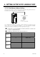
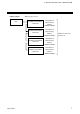
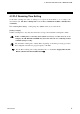
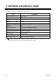
Table Of Contents
6 IMS01J04-E2
4.
SETTING ON THE H-PCP-J MODULE SIDE
4.1 PLC Data Memory Address Setting
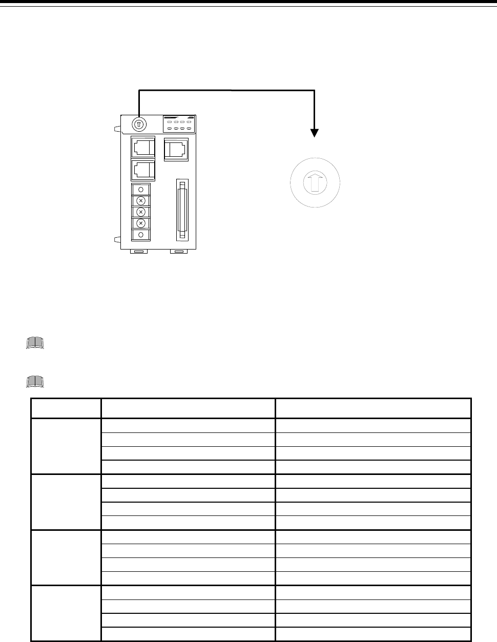
Set the data memory address of each control unit using the unit address setting switch at the front of
the H-PCP-J module. For this setting, use a small blade screwdriver.
8
7
6
5
4
3
2
1
0
F
E
D
C
B
A
9
H-PCP-J module
Setting range:
0 to 15 (0 to F: hexadecimal)
Unit address setting switch
Up to 4 SR Mini HG SYSTEMs can be connected to a PLC communication port. Therefore the data
memory address uses the 4 SR Mini HG SYSTEMs as a group. The SR Mini HG SYSTEMs
connected to the same PLC communication port sets the address in the same group.
Set unit address of each group including 0, 4, 8 and C by all means. 0, 4, 8 and C work
as a master of communication transfer.
Set unit address within address range of PLC (CPU unit) to use.
Group Unit address setting switch PLC data memory address
0
D1000 to D1499
Group 1
1
D1500 to D1999
2
D2000 to D2499
3
D2500 to D2999
4
D3000 to D3499
Group 2
5
D3500 to D3999
6
D4000 to D4499
7
D4500 to D4999
8
D5000 to D5499
Group 3
9
D5500 to D5999
A
D6000 to D6499
B
D6500 to D6999
C
D7000 to D7499
Group 4
D
D7500 to D7999
E
D8000 to D8499
F
D8500 to D8999