SR Mini HG SYSTEM Power Supply/CPU Module H-PCP-J PLC Communication Instruction Manual [For OMRON PLC] ® RKC INSTRUMENT INC.
Modbus is a registered trademark of Schneider Electric. The name of each programmable controller (PLC) means the products of each manufacturer. Company names and product names used in this manual are the trademarks or registered trademarks of the respective companies. All Rights Reserved, Copyright 2004, RKC INSTRUMENT INC.
Thank you for purchasing this RKC product. In order to achieve maximum performance and ensure proper operation of your new instrument, carefully read all the instructions in this manual. Please place the manual in a convenient location for easy reference. SYMBOLS WARNING : This mark indicates precautions that must be taken if there is danger of electric shock, fire, etc., which could result in loss of life or injury.
CAUTION This product is intended for use with industrial machines, test and measuring equipment. (It is not designed for use with medical equipment and nuclear energy.) This is a Class A instrument. In a domestic environment, this instrument may cause radio interference, in which case the user may be required to take additional measures. This instrument is protected from electric shock by reinforced insulation.
CONTENTS Page 1. OUTLINE ............................................................................... 1 2. COMMUNICATION SPECIFICATIONS ................................ 3 3. CONNECTIONS .................................................................... 4 4. SETTING ON THE H-PCP-J MODULE SIDE ....................... 6 4.1 PLC Data Memory Address Setting ................................................................. 6 4.2 Protocol Selection and Communication Setting ..................................
MEMO i-4 IMS01J04-E2
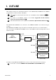
1. OUTLINE This manual describes the communication function of the SR Mini HG SYSTEM and the OMRON programmable controller (hereafter called PLC). This manual is attached when the model code of H-PCP-J module is H-PCP-J--D -03E. For details of the H-PCP-J module, see the Power Supply/CPU Module H-PCP-J Instruction Manual (IMS01J02-E). This manual should be used in conjunction with Hardware Quick Manual (IMS01V01-E).
1. OUTLINE Usable units (OMRON SYSMAC series) Name Type High-order link unit C200H-LK202-V1, C500-LK203, C120-LK202-V1 (SYSMAC C series), etc. CPU unit with a built in communication port CPU unit of SYSMAC CS1 series Serial communication board CS1W-SCB41 (SYSMAC CS1 series), etc. Usable modules (SR Mini HG SYSTEM) The following function module data can be used in PLC communication (see “Data map” on page 24). In addition, data on other modules connected (TI, AI, AO, etc.
2.
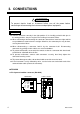
3. CONNECTIONS ! WARNING To prevent electric shock or instrument failure, turn off the power before connecting or disconnecting the instrument and peripheral equipment. CAUTION Connect connectors correctly in the right position. If it is forcibly pushed in with pins in the wrong positions, the pins may be bent resulting in instrument failure. When connecting or disconnecting the connectors, do not force it too far to right and left or up and down, but move it on the straight.
3. CONNECTIONS Connector pin number and signal details (RS-422A) Pin No. 1 2 3 4 5 6 Signal name Receive data Receive data Signal ground Send data Send data Signal ground Symbol R (A) R (B) SG T (B) T (A) SG Diagram of RS-422A wiring Pair wire H-PCP-J () (+) () PLC OMRON SYSMAC series T (A) 5 SDA T (B) 4 SDB SG 3 SG R (A) 1 RDA R (B) 2 RDB SG 6 (+) Shielded twisted pair wire The 6-pin type modular connector should be used for the connection to the H-PCP-J module.
4. SETTING ON THE H-PCP-J MODULE SIDE 4.1 PLC Data Memory Address Setting Set the data memory address of each control unit using the unit address setting switch at the front of the H-PCP-J module. For this setting, use a small blade screwdriver. Unit address setting switch 456 CD AB E 23 F01 7 89 Setting range: 0 to 15 (0 to F: hexadecimal) H-PCP-J module Up to 4 SR Mini HG SYSTEMs can be connected to a PLC communication port.
4.
4. SETTING ON THE H-PCP-J MODULE SIDE 4.2 Protocol Selection and Communication Setting Match the setting of data bit configuration, communication speed and communication protocol with the PLC communication specification by COM.PORT1/COM.PORT2 setting switch (SW2). Setting example to recommend is shown in the following. COM.PORT1/COM.PORT2 setting switch (SW2) H-PCP-J module ON 1 2 3 4 5 6 7 8 Data bit configuration Communication speed (Set the same as PLC.
4. SETTING ON THE H-PCP-J MODULE SIDE 4.3 PLC Scanning Time Setting Set the PLC scanning time (time of waiting for a response from the PLC) so as to adapt to the environment used. The PLC scanning time is set via host communication (RKC communication or Modbus). PLC scanning time setting Setting range: 0 to 3000 ms (Factory set value: 10 ms) [Setting example] Set PLC scanning time to any value more than twice as long as the maximum scanning time of PLC.
5. SETTING ON THE PLC SIDE Set the PLC as follows.
6. COMMUNICATION DATA 6.1 Request Command and Data Transfer Data transfer between PLC and SR Mini HG SYSTEM are executed by request command. Request command “0: Monitor (PLC SR Mini HG SYSTEM)” Command which status requests the SR Mini HG SYSTEM to write data such as temperature measured values, etc. (attribute: RO) to the PLC side. The SR Mini HG SYSTEM always repeats data writing until “1: Setting” or “2: Set value monitor” is set to the request command.
6. COMMUNICATION DATA Data transfer procedures Change each set value of SR Mini HG SYSTEM from the PLC after the initial settings are made. If each set value of SR Mini HG SYSTEM is changed from the PLC without setting the initial values, it is re-written to 0 with each set value of the PLC at that time set to 0.
6. COMMUNICATION DATA Data setting (When transmit data of temperature setting values from PLC to SR Mini HG SYSTEM) Start Set temperature set value (SV) and other setting data to each register (memory) in the PLC. Set “1” to the request command [Data setting] When 1 (Setting) is set to request command, the SR Mini HG SYSTEM starts reading the temperature set value data set to the register (memory) on the PLC side.
6. COMMUNICATION DATA Continued from the previous page. A Set “2” to the request command NO PCP communication state = 3 ? [Confirmation of setting data] When 2 (Set value monitor) is set to request command, the SR Mini HG SYSTEM starts writing the temperature set value data set to the PLC side. If 3 (Writing on setting data) is set to PCP communication state in the PLC, this indicates that SR Mini HG SYSTEM temperature set value data are being written into the PLC.
6. COMMUNICATION DATA 6.2 Data Processing Precautions With PLC communication, the maximum number of channels per unit address is 20. Read data of unused channel and undefined address is 0. The data type is treated as binary data with a sign and without a decimal point. For this reason, carefully express and set the data. (excluding the TIO status) [Example] Heat-side proportional band Initial value of internal data: 3.
6. COMMUNICATION DATA Some communication data may become invalid depending on the module selection or the configuration of the SR Mini HG System control unit. If any one of the conditions listed below occurs and data items written are within the setting range, read data becomes 0. Under these conditions, no error response message will occur. When heat/cool control, manual output value and auto/manual transfer are invalid.
6. COMMUNICATION DATA 6.3 Communication Data List Name : Item stored in the memory area. [ ]: The functional module name that data becomes valid is written. Attributes RO: At the time of request command “0: Monitor,” SR Mini HG SYSTEM writes in data. (SR Mini HG SYSTEM PLC) R/W: At the time of request command “1: Setting,” SR Mini HG SYSTEM read out data. At the time of request command “2: Set value monitor,” SR Mini HG SYSTEM writes in data.
6. COMMUNICATION DATA Continued from the previous page. Attribute Structure Heater break alarm set value [H-CT-A] R/W C 0.0 to 100.0 A or 0.0 to 30.0 A For the current transformer (CT) input of the H-CT-A module. Allocates the channels for H-TIO- module to the input channels of H-CT-A module by CT channel setting. For the CT channel setting, see the Power Supply/CPU Module H-PCP-J Instruction Manual (IMS01J02-E). 0.
6. COMMUNICATION DATA Continued from the previous page.
6. COMMUNICATION DATA Continued from the previous page. Conditions which will cause the autotuning to stop: When the temperature set value (SV) is changed. When the memory area is changed. When the PV bias value is changed. When the AT bias value is changed. When transfer to Manual mode using the Auto/Manual transfer.
6. COMMUNICATION DATA Continued from the previous page. Name Temperature measured value (PV) [H-TIO-, H-CIO-A] Attribute Structure RO C Motor speed measured value [H-SIO-A] Data range Factory set value TC/RTD input: Within input range Current/voltage input: Within display scale range Within display scale range Heat-side manipulated output value [H-TIO-, H-CIO-A] RO C 0.5 to 105.0 % Cool-side manipulated output value [H-TIO-, H-CIO-A] RO C 0.5 to 105.
6. COMMUNICATION DATA Continued from the previous page. Attribute Structure Request command [H-PCP-J] R/W U 0: Monitor Command which requests the SR Mini HG SYSTEM to write data such as temperature measured values, etc. (attribute: RO) to the PLC side. The SR Mini HG SYSTEM always repeats data writing until “1: Setting” or “2: Set value monitor” is set to the request command. The PCP communication status is set to “1: Writing on monitor data” during data transfer.
6. COMMUNICATION DATA Continued from the previous page. Name Attribute StrucData range ture U The numbers 0 and then 1 are repeated in every communication period. The SR Mini HG SYSTEM rewrites 0 and 1 in this area alternately like 0 1 0 in every communication period. It is possible to determine whether or not the SR Mini HG SYSTEM makes communication by monitoring this area periodically using the PLC program.
7. DATA MAP 7.1 Reference to Data Map This data map summarizes the data (data memory) addresses, channels and names that can be used with PLC. For details on each data range, see the 6.3 Communication Data List (P. 17).
7. DATA MAP 7.
7. DATA MAP Continued from the previous page.
7. DATA MAP Continued from the previous page.
7. DATA MAP Continued from the previous page.
7.
7. DATA MAP Continued from the previous page.
8. CURRENT TRANSFORMER (CT) MONITOR Current transformer (CT) monitor function monitors only current transformer input. Control unit is configured with H-PCP-J module and H-CT-A module to do current transformer (CT) monitor. Data of functional module other than the H-CT-A module cannot be used. In addition, set the communication protocol to “OMRON SYSMAC series special protocol [Current transformer (CT) monitor].
8. CURRENT TRANSFORMER (CT) MONITOR Current transformer (CT) monitor dedicated system configuration SR Mini HG SYSTEM control unit H-CT-A module H-PCP-J (10 modules max.) module PLC OMRON SYSMAC series RS-422A RS-422A SR Mini HG SYSTEM control unit H-CT-A module H-PCP-J (10 modules max.
8. CURRENT TRANSFORMER (CT) MONITOR 8.1 Setting on The H-PCP-J Module Side PLC data memory address setting Set the data memory address of each control unit using the unit address setting switch at the front of the H-PCP-J module. For this setting, use a small blade screwdriver. Unit address setting switch 456 CD AB E 23 F01 7 89 Setting range: 0 to 15 (0 to F: hexadecimal) H-PCP-J module Up to 16 SR Mini HG SYSTEMs can be connected to a PLC communication port.
8. CURRENT TRANSFORMER (CT) MONITOR Continued from the previous page.
8. CURRENT TRANSFORMER (CT) MONITOR Protocol selection and communication setting Match the setting of data bit configuration, communication speed and communication protocol with the PLC communication specification by COM.PORT1/COM.PORT2 setting switch (SW2). Setting example to recommend is shown in the following. COM.PORT1/COM.PORT2 setting switch (SW2) H-PCP-J module ON 1 2 3 4 5 6 7 8 Data bit configuration Communication speed (Set the same as PLC.
8. CURRENT TRANSFORMER (CT) MONITOR PLC scanning time setting Set the PLC scanning time (time of waiting for a response from the PLC) so as to adapt to the environment used. The PLC scanning time is set via host communication (RKC communication or Modbus). PLC scanning time setting Setting range: 0 to 3000 ms (Factory set value: 10 ms) [Setting example] Set PLC scanning time to any value more than twice as long as the maximum scanning time of PLC.
8. CURRENT TRANSFORMER (CT) MONITOR 8.2 Setting on The PLC Side Set the PLC as follows.
8. CURRENT TRANSFORMER (CT) MONITOR 8.3 Communication Data List Attributes RO: SR Mini HG SYSTEM writes in data. (SR Mini HG SYSTEM PLC) If the power is turned on, SR Mini HG SYSTEM always writes data to PLC. As for the setting of request command from PLC, there is not requirement. The data type is treated as binary data with a sign and without a decimal point. [Example] Current transformer input measured value Initial value of internal data: 12.
The first edition: SEP. 2004 [IMQ00] The second edition: FEB.
R RKC INSTRUMENT INC. HEADQUARTERS: 16-6, KUGAHARA 5-CHOME, OHTA-KU TOKYO 146-8515 JAPAN PHONE: 03-3751-9799 (+81 3 3751 9799) FAX: 03-3751-8585 (+81 3 3751 8585) E-mail: info@rkcinst.co.jp Website: http://www.rkcinst.com/ IMS01J04-E2 FEB.