
Specifications
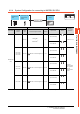

4. CONNECTION TO FUJI PLC
4.2 Serial connection
4 - 13
4
CONNECTION TO FUJI PLC
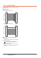
RS-485 cable
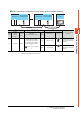
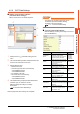
(1) RS-485 connection diagram 1)
*1 Turn ON the terminating switch of a interface converter which will be a terminal.
*2 Set the terminating resistor of GOT side which will be a terminal.
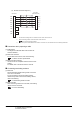
■ Connecting terminating resistors
*3 Connect FG grounding to the appropriate part of a cable shield line.
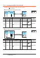
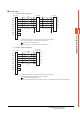
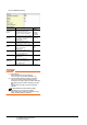
(2) RS-485 connection diagram 2)
*1 Turn ON the terminating switch of a interface converter which will be a terminal.
*2 Set the terminating resistor of GOT side which will be a terminal.
■ Connecting terminating resistors
*3 Make sure to pull the cable shield line into inside the connector cover, and treat the line end for obtaining shield effect.
PLC side
*
1
GOT side
*
2
RDA
RDB
SDA
SDB
SG
RSA
CSA
RSB
CSB
SDA
SDB
RDA
RDB
SG
FG
SDA
SDB
RDA
RDB
SG
FG
2
7
1
6
5
3
4
8
9
-
PLC side
*
1
*
3
*
3
SDA(+)
SDB(-)
RDA(+)
RDB(-)
SG
FG
2
1
9
8
5
6
GOT side
*
2
RDA
RDB
SDA
SDB
SG
RSA
CSA
RSB
CSB
2
7
1
6
5
3
4
8
9
-
PLC side
*1
(D-sub 9-pin)
*
3