
Specifications

3 - 8
3. CONNECTION TO HITACHI PLC
3.6 Device Range that Can Be Set
3.6 Device Range that Can Be Set
The device ranges of controller that can be used for GOT
are as follows.
Note that the device ranges in the following tables are the
maximum values that can be set in GT Designer3.
The device specifications of controllers may differ
depending on the models, even though belonging to the
same series.
Please make the setting according to the specifications of
the controller actually used.
When a non-existent device or a device number outside
the range is set, other objects with correct device settings
may not be monitored.
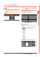
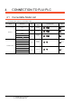
Setting item
*1 The uppermost bit is b0 and the lowermost bit is b15.
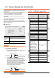
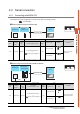
POINTPOINTPOINT
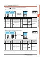
Device settings of HITACHI PLC
(1) When setting a bit device
Set the device using the format of address (word
unit) + bit number (0 to F).
(2) When setting a word device
For external input (XW), external output (YW),
internal register (RW), extended internal register
(MW, AW), keep relay (KW), on-delay timer (TW),
one-shot timer (UW), up-down counter (CW),
global link register (GW), event register (EW),
system register (SW), transfer register (JW), and
receive register (QW), set as follows.
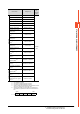
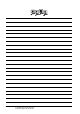
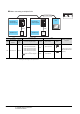
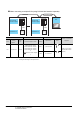
3.6.1 HITACHI S10mini/S10V
Item Information
Device
*1
Set the device name, device number, and bit number.
The bit number can be set only when specifying the bit
of word device.
Information
Displays the device type and setting range which are
selected in [Device].
Bit position (0 to F)
Address (word units)
Device name
Fixed to 0
Address (word units)
Device name
Device name Setting range
Device
No.
represen
tation
Bit device
External input (X) X000 to XFFF
Hexadec
imal
External output (Y) Y000 to YFFF
Internal register (R) R000 to RFFF
Keep relay (K) K000 to KFFF
Extended internal register
(M)
M000 to MFFF
Extended internal register
(A)
A000 to AFFF
On-delay timer (T) T000 to T1FF
One-shot timer (U) U000 to U0FF
Up-down counter (C) C00 to CFF
Global link register (GL)
*6
GL000 to GLFFF
Event register (E) E000 to EFFF
System register (S)
*1
S000 to SBFF
Transfer register (J) J000 to JFFF
Receive register (Q) Q000 to QFFF
The bit specification of the
word device (except
External input, External
output, Internal register,
Extended internal register,
Keep relay, On-delay timer,
One-shot timer, Up/Down
counter, Global link
register, Event register,
System register, Transfer
register, Receive register)
Setting range of each word
device
―
Word device
External input (XW) XW000 to XWFF0
Hexadec
imal
External output (YW) YW000 to YWFF0
Internal register (RW) RW000 to RWFF0
Extended internal register
(MW)
MW000 to MWFF0
Extended internal register
(AW)
AW000 to AWFF0
Keep relay (KW) KW000 to KWFF0
On-delay timer (TW) TW000 to TW1F0