
Specifications

3. CONNECTION TO HITACHI PLC
3.3 Connection Diagram
3 - 5
3
CONNECTION TO HITACHI PLC
3.3 Connection Diagram
The following diagram shows the connection between the
GOT and the PLC.
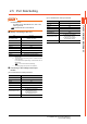
3.3.1 RS-232 cable
Connection diagram
Precautions when preparing a cable
(2) Cable length
The length of the RS-232 cable must be 15m or less.
(3) GOT side connector
For the GOT side connector, refer to the following.
1.4.1GOT connector specifications
(4) HITACHI PLC side connector
Use the connector supporting the HITACHI PLC side
module.
For details, refer to the HITACHI PLC user's manual.
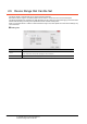
3.3.2 RS-422 cable
Connection diagram
Precautions when preparing a cable
(2) Cable length
The length of the RS-422 cable must be 500m or less.
(3) GOT side connector
For the GOT side connector, refer to the following.
1.4.1GOT connector specifications
(4) HITACHI PLC side connector
Use the connector compatible with the HITACHI PLC
side module.
For details, refer to the HITACHI PLC user's manual.
Connecting terminating resistors
(1) GOT side
When connecting a PLC to the GOT, a terminating
resistor must be connected to the GOT.
For the procedure to set the terminating resistor, refer
to the following.
1.4.3Terminating resistors of GOT
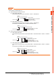
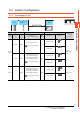
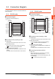
(1) RS-232 connection diagram 1)
For the GT16, GT15
*1 Connect FG grounding to the appropriate part of a cable
shield line.
GOT side
(D-sub 9-pin)
CD
RD(RXD)
SD(TXD)
ER(DTR)
SG
DR(DSR)
RS(RTS)
CS(CTS)
-
RS
SD
RD
DR
SG
ER
CD
CS
-
*
1
1
2
3
4
5
6
7
8
9
7
3
2
6
5
4
1
8
9
PLC side
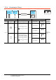
(1) RS-422 connection diagram 2)
*1 Connect FG grounding to the appropriate part of a cable
shield line.
GOT side
SDA
RDA
RSA
CSA
SG
SDB
RDB
RSB
CSB
RD-H
SD-H
-
ATT-H
SG
RD-L
SD-L
-
ATT-L
*
1
1
2
3
4
5
6
7
8
9
2
3
6
7
5
1
4
8
9
PLC side