
Specifications

2 - 14
2. CONNECTION TO HITACHI IES PLC
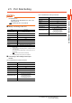
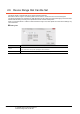
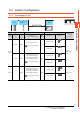
2.6 Device Range that Can Be Set
2.6.1 HITACHI HIDIC H Series
*1 Overlapped numbers cannot be used.
*2 Do not set device outside the range.
If the set device is outside the range, the object set by the device within the range may not be displayed.
Device name Setting range Device No. representation
Bit device
External input (X) X00000 to X05A95
Hexadecimal + Decimal
External output (Y) Y00000 to Y05A95
Remote external input (X) X10000 to X49995
Decimal
Remote external output (Y) Y10000 to Y49995
1st CPU link (L) L0000 to L3FFF
Hexadecimal2nd CPU link (L1) L10000 to L13FFF
Data area (M) M0000 to M3FFF
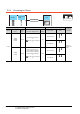
On-delay timer (TD)
*1
TD0 to TD255
Decimal
Single-shot timer (SS)
*1
SS0 to SS255
Watchdog timer (WDT)
*1
WDT0 to WDT255
Monostable timer (MS)
*1
MS0 to MS255
Retentive timer (TMR)
*1
TMR0 to TMR255
Up counter (CU)
*1
CU0 to CU511
Ring counter (RCU)
*1
RCU0 to RCU511
Up/Down counter (CT)
*1
CT0 to CT511
Bit internal output (R) R0 to R7BF Hexadecimal
Rising edge detection (DIF)
*1
DIF0 to DIF511
Decimal
Falling edge detection (DFN)
*1
DFN0 to DFN511
The bit specification of the word device
(except External input, External output,
Remote external input, Remote external
output, 1st CPU link, 2nd CPU link, Data
area)
Setting range of each word device ―
Word device
External input (WX) WX0000 to WX05A7
Hexadecimal + Decimal
External output (WY) WY0000 to WY05A7
Remote external input (WX) WX1000 to WX4997
Decimal
Remote external output (WY) WY1000 to WY4997
First CPU link (WL) WL000 to WL3FF
Hexadecimal2nd CPU link (WL1) WL1000 to WL13FF
Data area (WM) WM000 to WM3FF
Timer/Counter (Elapsed value) (TC)
*1
TC0 to TC511 Decimal
Word internal output (WR) WR000 to WR3FF Hexadecimal