
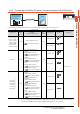
Specifications


2. CONNECTION TO HITACHI IES PLC
2.3 Connection Diagram
2 - 7
2
CONNECTION TO HITACHI IES PLC
2.3 Connection Diagram
The following diagram shows the connection between the
GOT and the PLC.
2.3.1 RS-232 cable
Connection diagram
Precautions when preparing a cable
(3) Cable length
The length of the RS-232 cable must be 15m or less.
(4) GOT side connector
For the GOT side connector, refer to the following.
1.4.1GOT connector specifications
(5) HITACHI IES PLC side connector
Use the connector compatible with the HITACHI IES
PLC side module.
For details, refer to the HITACHI IES PLC user's
manual.
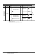
2.3.2 RS-422 cable
Connection diagram
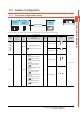
(1) RS-232 connection diagram 1)
*1 GT16: CD, GT15: CD, GT14: NC, GT12: NC, GT11: NC
(2) RS-232 connection diagram 2)
*1 GT16: CD, GT15: CD, GT14: NC, GT12: NC, GT11: NC
GOT side HITACHI IES PLC side
NC
SD
RD
RV2(DR)
SG
CS
RV1(ER)
RS
PHL
FG
CD/NC
*
1
RD(RXD)
SD(TXD)
ER(DTR)
SG
DR(DSR)
RS(RTS)
CS(CTS)
-
1
2
3
4
5
6
7
8
9
1
2
3
7
9
5
6
4
8
FG
GOT side HITACHI IES PLC side
NC
SD
RD
RV2(DR)
SG
CS
RV1(ER)
RS
PHL
ER
FG
CD/NC
*
1
RD(RXD)
SD(TXD)
ER(DTR)
SG
DR(DSR)
RS(RTS)
CS(CTS)
-
1
2
3
4
5
6
7
8
9
1
2
3
7
9
5
6
4
8
14
FG
(1) RS-422 connection diagram 1)
GOT side
RDA
RDB
SDA
SDB
RSA
RSB
CSA
CSB
-
SG
-
FG
2
7
1
6
3
8
4
9
-
5
-
-
TXDP
TXDN
RXDP
RXDN
TXDG
-
-
-
-
RXDG
-
-
HITACHI IES PLC side
R