
Specifications

1. PREPARATORY PROCEDURES FOR MONITORING
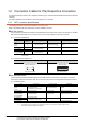
1.4 Connection Cables for the Respective Connection
1 - 23
1
PREPARATORY PROCEDURES FOR MONITORING
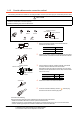
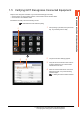
1.4.3 Terminating resistors of GOT
The following shows the terminating resistor specifications on the GOT side.
When setting the terminating resistor in each connection type, refer to the following.
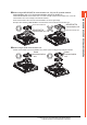
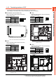
RS-422/485 communication unit
Set the terminating resistor using the terminating
resistor setting switch.
*1 The default setting is "Disable".
• For RS422/485 communication unit
GT27
Set the terminating resistor using the terminating
resistor setting switch.
*1 The default setting is "Disable".
• For GT2710-V
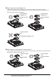
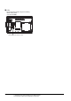
GT25
Set the terminating resistor using the terminating
resistor setting switch.
*1 The default setting is "Disable".
• For GT2510-V
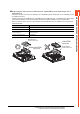
GT23
Set the terminating resistor using the terminating
resistor setting switch.
*1 The default setting is "Disable".
• For GT2310-V
Terminating
resistor
*1
Switch No.
1 2
100 OHM ON ON
Disable OFF OFF
Terminating
resistor
*1
Switch No.
1 2
100 OHM ON ON
Disable OFF OFF
SW1
ON
1 2
ON
SW1
ON
12
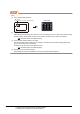
Rear view of RS-422/485 communication unit.
Terminating resistor setting switch
ON
12
Terminating resistor setting switch
(inside the cover)
Terminating
resistor
*1
Switch No.
1 2
100 OHM ON ON
Disable OFF OFF
Terminating
resistor
*1
Switch No.
1 2
100 OHM ON ON
Disable OFF OFF
ON
12
Terminating resistor setting switch
(inside the cover)
ON
12
Terminating resistor setting switch
(inside the cover)