
Specifications

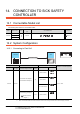

13. CONNECTION TO MITSUBISHI INDIA PLC
13.3 Connection Diagram
13 - 9
CONNECTION TO MITSUBISHI INDIA PLC
13
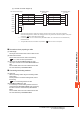
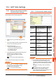
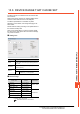
(3) RS-485 connection diagram 3)
*1 Set the terminating resistor to “Enable” when arranging the GOT in the end position of the system configuration.
Set the terminating resistor to “Disable” when arranging the GOT in any position other than the end position of the system
configuration. 1.4.3 Terminating resistors of GOT
*2 For terminating resistors in PLCs manufactured by MITSUBISHI INDIA, refer to the manual of PLCs manufactured by
MITSUBISHI INDIA.
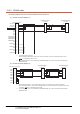
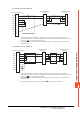
(4) RS-485 connection diagram 4)
*1 Set the terminating resistor to “Enable” when arranging the GOT in the end position of the system configuration.
Set the terminating resistor to “Disable” when arranging the GOT in any position other than the end position of the system
configuration. 1.4.3 Terminating resistors of GOT
*2 For terminating resistors in PLCs manufactured by MITSUBISHI INDIA, refer to the manual of PLCs manufactured by
MITSUBISHI INDIA.
*3 The signals RSA, RSB, CSA, and CSB are not provided for . Return connection is not required.
GOT side (terminal block)
*1
SDA1
SDB1
RDA1
RDB1
SDA2
SDB2
RDA2
RDB2
SG
FG
1
2
3
4
5
6
7
8
9
10
4
7
9
8
5
Tx +
Tx –
Rx +
Rx –
GND
Tx +
Tx –
Rx +
Rx –
GND
4
7
9
8
5
MITSUBISHI INDIA
PLC side
*2
MITSUBISHI INDIA
PLC side
*2
GOT side (terminal block)
*1
SDA
SDB
RDA
RDB
SG
RSA
RSB
CSA
CSB
*3
*3
*3
*3
4
7
9
8
5
Tx +
Tx –
Rx +
Rx –
GND
4
7
9
8
5
Tx +
Tx –
Rx +
Rx –
GND
MITSUBISHI INDIA
PLC side
*2
MITSUBISHI INDIA
PLC side
*2