
Specifications


13 - 6
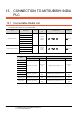
13. CONNECTION TO MITSUBISHI INDIA PLC
13.3 Connection Diagram
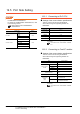
13.3.2 RS-422 cable
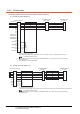
The following diagram shows the connection between the GOT and the PLC.
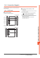
(1) RS-422 connection diagram 1)
*1 A terminating resistor is required.
Set the terminating resistor selector switch in the main unit to “Disable”, and connect a terminating resistor (110 Ω).
1.4.3 Terminating resistors of GOT
*2 For terminating resistors in PLCs manufactured by MITSUBISHI INDIA, refer to the manual of PLCs manufactured by
MITSUBISHI INDIA.
*3 Use a twisted pair cable for the SDA1/SDB1.
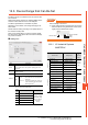
(2) RS-422 connection diagram 2)
*1 A terminating resistor is required.
In the GT27, set the terminating resistor selector switch in the main unit to “Disable”, and connect a terminating resistor (330 Ω).
1.4.3 Terminating resistors of GOT
*2 For terminating resistors in PLCs manufactured by MITSUBISHI INDIA, refer to the manual of PLCs manufactured by
MITSUBISHI INDIA.
CON side (20 pin)
*1
SG
NC
NC
NC
SDA2(TXD2+)
SDB2(TXD2-)
RDA2(RXD2+)
RDB2(RXD2-)
NC
RSA(RTS+)
NC
RSB(RTS-)
NC
CSA(CTS+)
NC
CSB(CTS-)
SDA1(TXD1+)
*3
SDB1(TXD1-)
*3
RDA1(RXD1+)
*3
RDB1(RXD1-)
*3
6
8
10
12
2
1
3
4
5
7
9
11
13
14
15
16
17
18
19
20
MITSUBISHI INDIA
PLC side
*2
Tx +
Tx –
Rx +
Rx –
GND
*1
R
*1
R
4
7
9
8
5
4
7
9
8
5
Tx +
Tx –
Rx +
Rx –
GND
MITSUBISHI INDIA
PLC side
*2
GOT side (D-sub 9 pin)
*1
SG
RSA
RSB
CSA
CSB
SDA
SDB
RDA
RDB
1
6
2
7
5
3
8
4
9
*1-
*1
R
R
MITSUBISHI INDIA
PLC side
*2
4
7
9
8
5
4
7
9
8
5
Tx +
Tx –
Rx +
Rx –
GND
Tx +
Tx –
Rx +
Rx –
GND
MITSUBISHI INDIA
PLC side
*2