
Specifications

12. CONNECTION TO LS INDUSTRIAL SYSTEMS PLC
12.3 Connection Diagram
12 - 9
CONNECTION TO LS INDUSTRIAL SYSTEMS PLC
12
12.3 Connection Diagram
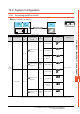
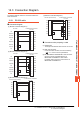
The following diagram shows the connection between the
GOT and the PLC.
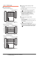
12.3.1 RS-232 cable
Connection diagram
Precautions when preparing a cable
(1) Cable length
The length of the RS-232 cable must be 15m or less.
(2) GOT side connector
For the GOT side connector, refer to the following.
1.4.1 GOT connector specifications
(3) LS INDUSTRIAL SYSTEMS PLC side connector
Use the connector compatible with the LS
INDUSTRIAL SYSTEMS PLC side module.
For details, refer to the user's manual of the LS
INDUSTRIAL SYSTEMS PLC.
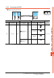
(1) RS-232 connection diagram 1)
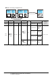
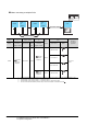
(2) RS-232 connection diagram 2)
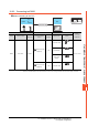
(3) RS-232 connection diagram 3)
1
2
3
4
5
6
7
8
9
LS INDUSTRIAL SYSTEM
PLC side
GOT side
1
7
4
2
5
3
6
8
9
CD
RD(RXD)
SD(TXD)
ER(DTR)
SG
DR(DSR)
RS(RTS)
CS(CTS)
NC
5V
TXD2
RXD2
RXD1
SG
TXD1
5V
SG
SG
1
2
3
4
5
6
7
8
9
LS INDUSTRIAL SYSTEM
PLC side
GOT side
1
3
2
4
5
6
7
8
9
CD
RD(RXD)
SD(TXD)
ER(DTR)
SG
DR(DSR)
RS(RTS)
CS(CTS)
NC
CD
TXD
RXD
DTR
SG
DSR
RTS
CTS
-
LS INDUSTRIAL SYSTEMS
PLC side
GOT side (terminal block)
4
7
1
2
5
3
6
8
9
SD
RD
ER
DR
SG
RS
CS
RXD2
TXD2
5V
RXD1
SG
TXD1
5V
SG
SG
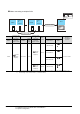
(4) RS-232 connection diagram 4)
LS INDUSTRIAL SYSTEMS
PLC side
GOT side (terminal block)
2
3
1
4
5
6
7
8
9
SD
RD
ER
DR
SG
RS
CS
RXD
TXD
CD
DTR
SG
DSR
RTS
CTS
-