
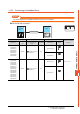
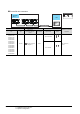
Specifications


11. CONNECTION TO GE PLC
11.3 Connection Diagram
11 - 11
CONNECTION TO GE PLC
11
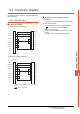
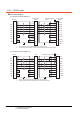
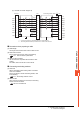
(3) RS-422 connection diagram 3)
*1 Connect FG grounding to the appropriate part of a cable shield line.
*2 Terminating resistor should be provided for a PLC which will be a terminal.
Precautions when preparing a cable
(1) Cable length
The length of the RS-422 cable must be 1200m or less.
(2) GOT side connector
For the GOT side connector, refer to the following.
1.4.1 GOT connector specifications
(3) GE PLC side connector
Use the connector compatible with the GE PLC side
module.
For details, refer to the GE PLC user's manual.
Connecting terminating resistors
(1) GOT side
Set the terminating resistor setting switch of the GOT
main unit to "Disable".
For the procedure to set the terminating resistor, refer
to the following.
1.4.3 Terminating resistors of GOT
(2) GE PLC side
When connecting a GE PLC to the GOT, a terminating
resistor must be connected.
GE PLC user's Manual
GOT side
PLC PLC
RT
RD(B’)
RD(A’)
SD(B)
SD(A)
SG
RTS(A)
CTS(A’)
RTS(B)
CTS(B’)
SHLD
9
11
10
13
12
7
6
15
14
8
1
RT
RD(B’)
RD(A’)
SD(B)
SD(A)
SG
RTS(A)
CTS(A’)
RTS(B)
CTS(B’)
SHLD
9
11
10
13
12
7
6
15
14
8
1
*
1
terminating resistor 120Ω
*
2
SDA
SDB1
RDA
RDB
SG
RSA
CSA
RSB
CSB
1
6
2
7
5
3
4
8
9
*
1